 kWhik
kWhikVault-4 (Gen-1)
A PowerVault is a weather-resistant chest that provides for safe electrical usage outside the confines of a sheltering building. More details about the vault design in general is in PowerVault Gen-1
Vault-4 is a 48V solar harvester and has some notable differences from Vault-1:
- Larger vault (24x24xWidth) to hold 3+ 19” Rack batteries
- 4-level partial-span shelving to maximize non-battery space
- Significant levels of insulation
- Only DC (harvesting) circuitry but with multiple MPPTs
- Large conduit connection for high-amperage DC out (to Vault-5) as well as smaller conduit and anderson PP connectors to provide lower amperage DC to systems like Vault-1
- Semi-transplant and non-structural electrical box with status lights (as opposed to the structural version in Vault-1)
- A BRB (Big-Red-Button) for rapid shutdown
Vault-4 transformed later into just the BESS portion with Vault-6 taking on the collector responsibilities. This description is for before that transformation.
Table of Contents
System Overview
Vault-4 is a 48V harvester (48V BESS + solar collector) designed for:
- 300Ah (15kWh) of rack batteries
- Insulated well enough to deal with -20°C without signficiant energy cost
- Space for multiple MPPTs
- High-amperage (300A+) DC-out
- Multiple lower amperage DC-outs
- Monitoring, control, display, etc.
The conspicuously missing item is any AC capabilities. This is intentional: by keeping the battery and DC system separate from the AC inverters, significant insulation can be provided for dealing with external temperatures without needing to dissipate the high heat produced by inverters. It also makes the system able easier to manage and control: simply dc-ins, battery-energy/soc, dc-outs. Further, it provides the ability to easily cascade a 48V system as a virtual 24-hour ‘solar source’ at low amperage (e.g. <30A) but with high total energy movement (1500W * 24-hours = 36kWh per day).
Some pictures are below: note that these are pictures of running (and fiddling) systems, please excuse the mess :-)
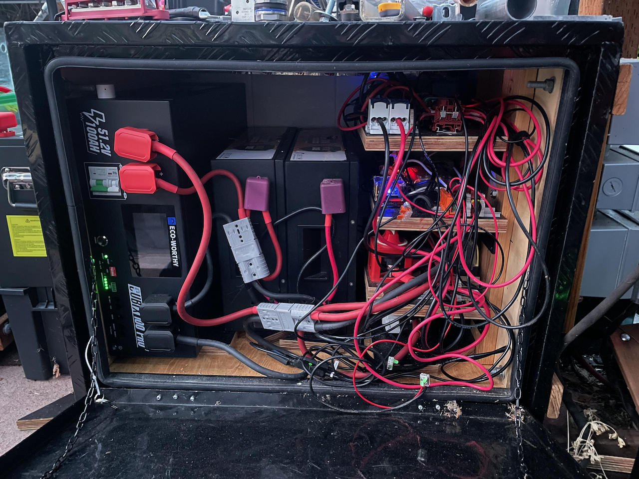
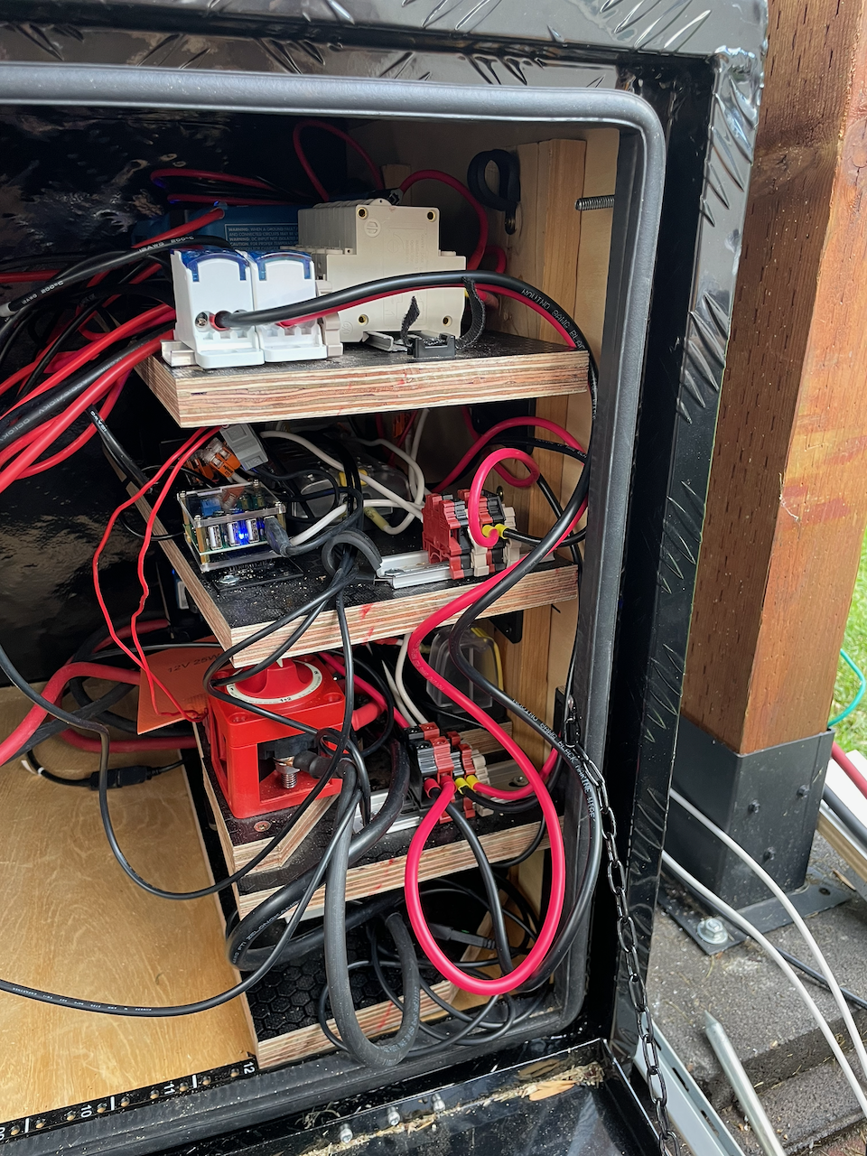
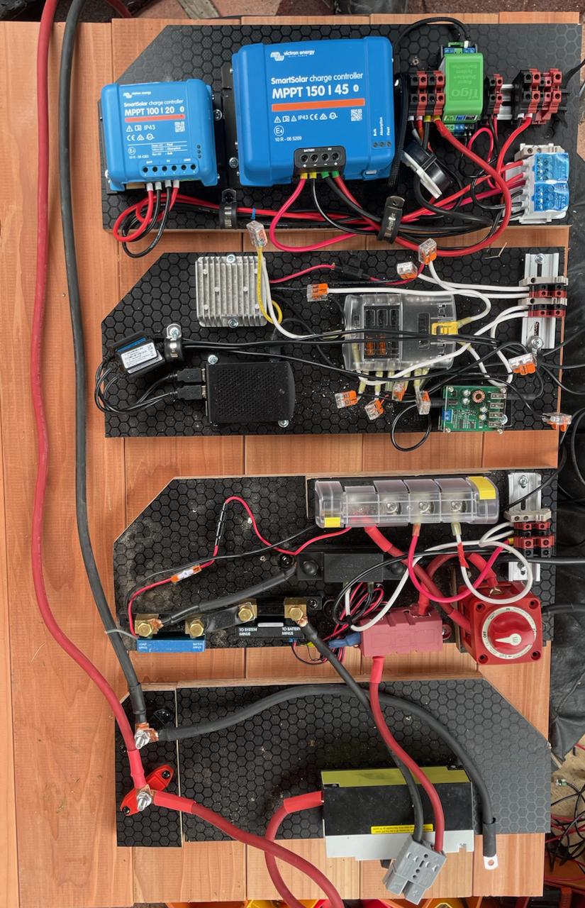
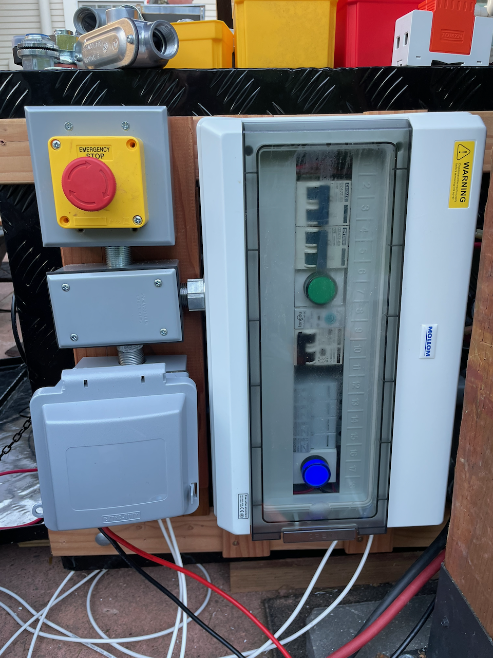
Core Structural Aspects
A Vault is structurally based on Truck “Tool Boxes”. Vault-4 is an aluminum 24”x24”x30” (depth-height-width) Underbody Tool Box and specifically this product: 30”x 24”x 24” Truck Box
To transform the Tool Box into a Vault we need to:
- Frame the inside
- Frame the outside
- Connect between the two
Framing the inside
Compared to Vault-1, the main addition to the inside framing is insulation on the sides, top, and rear. Insulation can also be put into the door but Vault-4 does not have this currently, so I will write it up when it is finished. The thermal loss through the door is low enough that no significant energy (heating) was expended on compensating for it.
The floor and ‘control-side’ walls are 1.5” XPS due to structural aspects (PSIs) associated with these sides. The floor could have more than 300lbs on it, and although this is only 1-PSI when everything is stable, forces could be much higher when moving batteries into the vault. The control-side (‘right’ for Vault-4) wall has insulation compressed between the inner wall and the tool box side, and this needs to have sufficient compressive strength when the walls-and-rails are torqued to each other to support loads on the inside (shelves) and outside (electrical boxes).
The other sides (left, back, top) use ½” Polyiso to get a similar R-value to the XPS while using less space. Fitting the 19” rack batteries used (Eco-Worthy Cubix) required as much depth as possible (Cubix are ~22” deep), and rack batteries in general tend to require 18” for three of them side-by-side. The savings of half-inches with the polyiso made this possible while keeping the control-shelving a usable width.
Framing the outside
The outside of Vault-4 is almost identical to Vault-1 except the dimensions are larger and there is a much larger 1.5” rigid pipe fitting for higher-amperage cabling.
Connecting the inside to the outside
Connecting the inside to the outside of Vault-4 is identical to Vault-1: the ¾” conduit is used to interconnect the inside to a watertight junction box on the outside and that allows interconnection to the electrical boxes.
The Main Structural Build
The following will describe the steps for the main structural build, but especially focus on the differences from Vault-1.
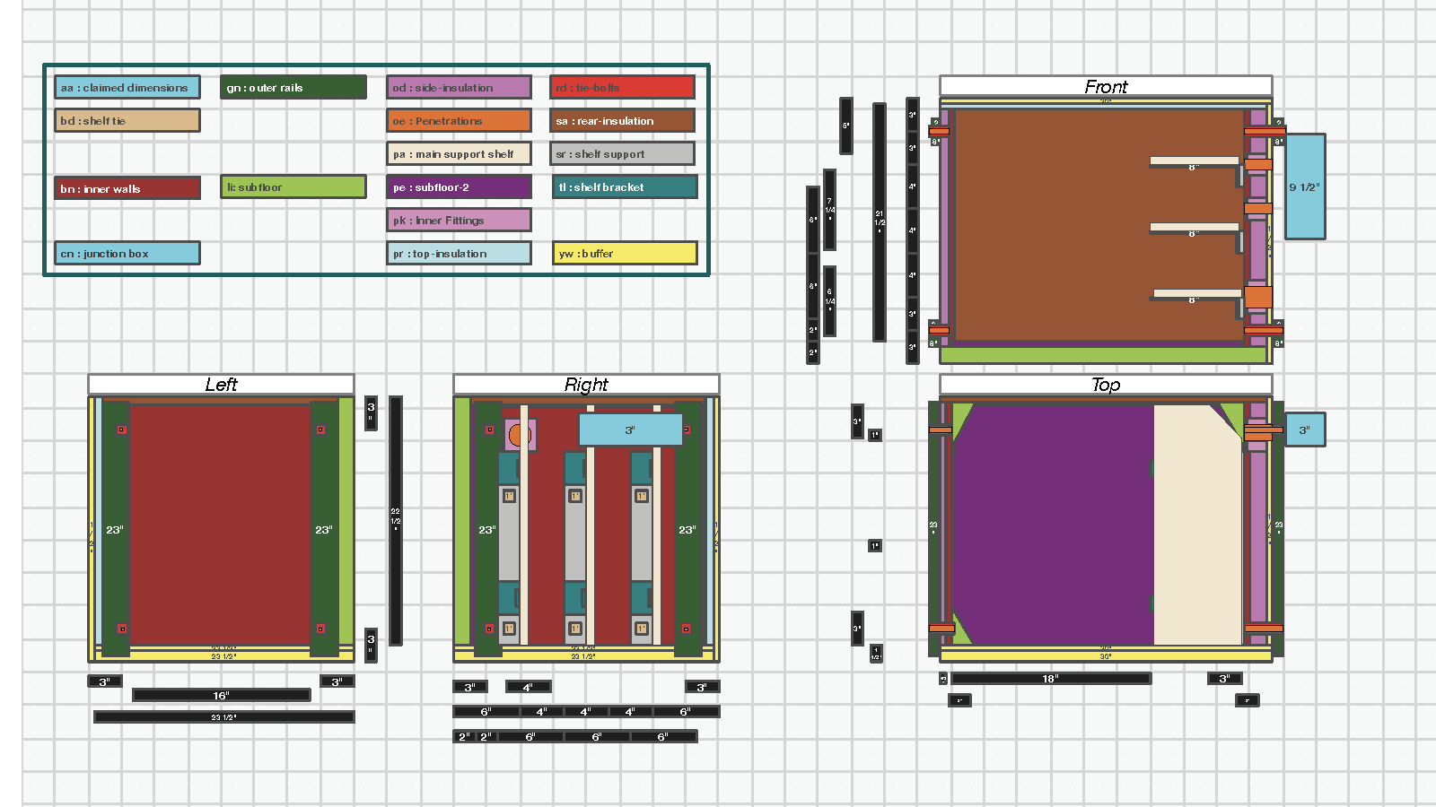
The final version up through the external junction boxes looks like this:
Base Tool Box dimensions
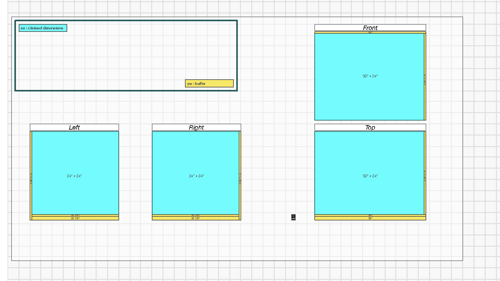
The Vault-4 24x24x30 toolbox has a different kind of ‘neck’ from Vault-1: it is invisible with the door closed, but the door framing is an inset that penetrates into the useable space. So the compensation is basically the same: to put a 1” buffer on the door side. There is a bit of space around the edge, so insulation could be put around the inset, but it would be very tight (could be done with expanding foam if desired).
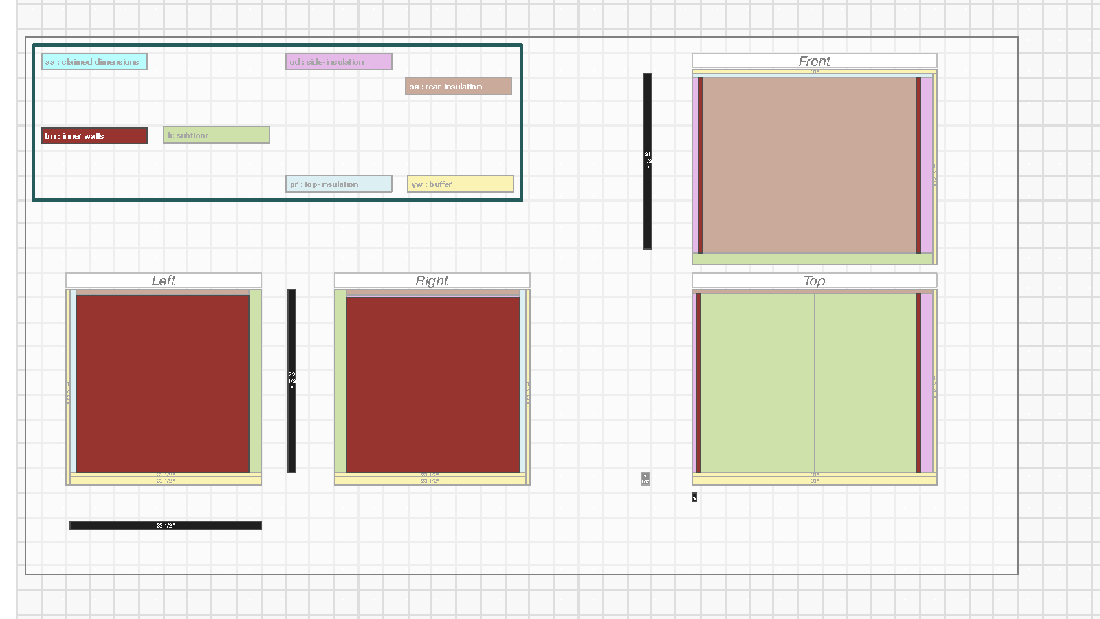
Subfloors, Insulation, and Inner Walls
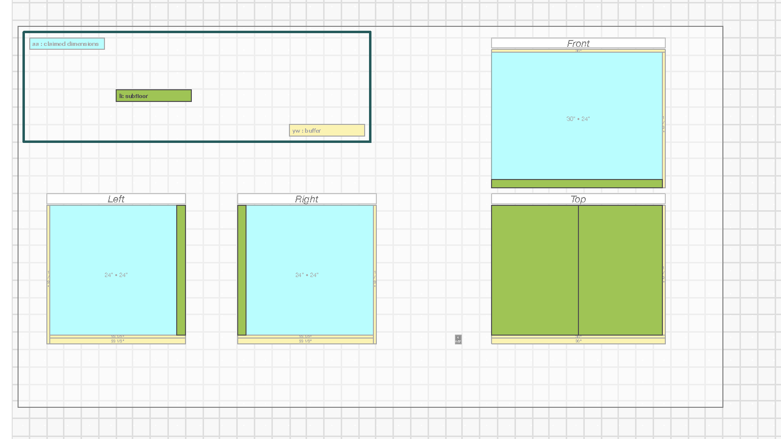
The subfloor is the same as Vault-1. As mentioned above, the use of XPS is for the potential forces associated with 100lb batteries, and by lifting the floor to the neck height it is much easier to get these heavy object into and out of the box.
Insulation
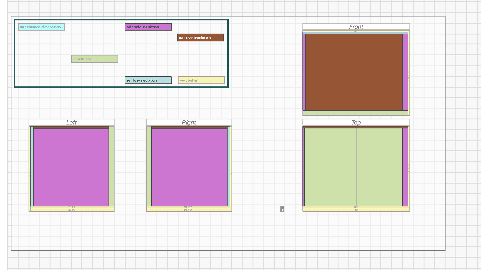
The insulation for Vault-4 extends around three sides and the ceiling with the control-side (‘right’) having the thicker 1.5” XPS for structural/compression support and the other sides having ½” Polyiso insulation. The Polyiso is taped on its edges to avoid stripping pieces out of it.
Inner Walls
The inner walls are the same as Vault-1.
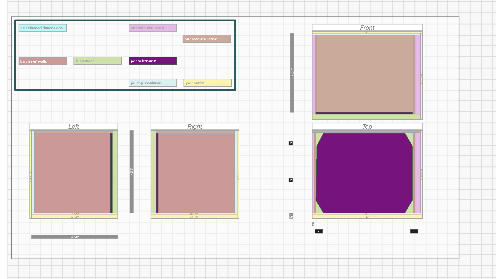
Subfloor-2
The second subfloor for Vault-4 is the same as for Vault-1, but is more critically important as it lifts the floor up to the bottom of the neck for the 100lb batteries and helps absorb impacts during the loading process.
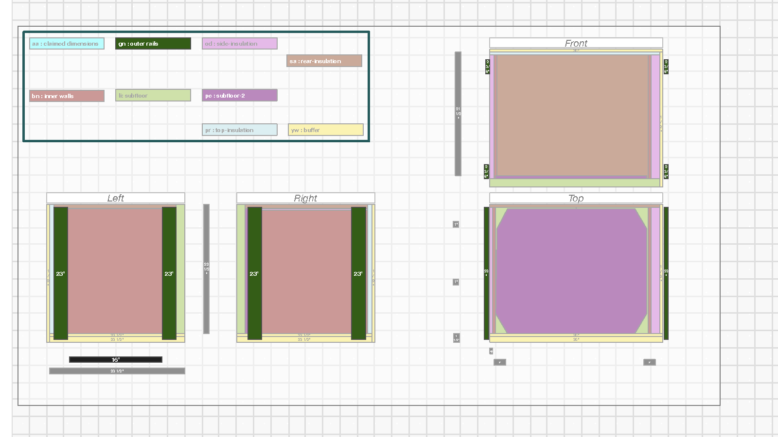
Outer Rails and Tie-Bolts
The outer rails and the tie-bolts are the same as for Vault-1.
You might consider adding an additional (middle) rail on the control-side (right-side for Vault-4) and tie-bolt locations in nine vs. four locations if the weight of anything on the inside or outside seemed beyond the range the compressed sandwich (plywood, insulation, aluminum, rail) could handle with just four bolts, but I have not encountered an issue yet.
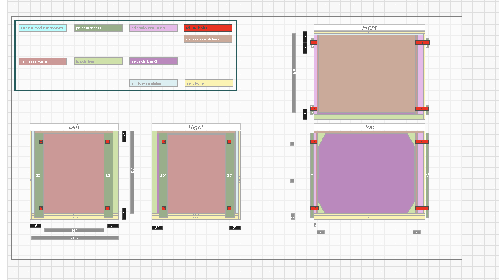
Tie-Bolts
See: Vault-1 for diagram explanation.
Inner Fittings and Penetrations
The inner fittings and penetrations are the same approach as for Vault-1, with the notable addition of the 1.5” conduit fitting that comes out of the right-side bottom location. This fitting has enough clearance from the bottom rail to not collide with it, and is offset an additional half-inch inward from the back (so 3.5” vs. 3”) to make sure it has two inches of clearance from the back. This 2” clearance allows 1.5” of insulation at the back if additional thermal protection is needed and space allows (other rack batteries are shallower than the Cubix).
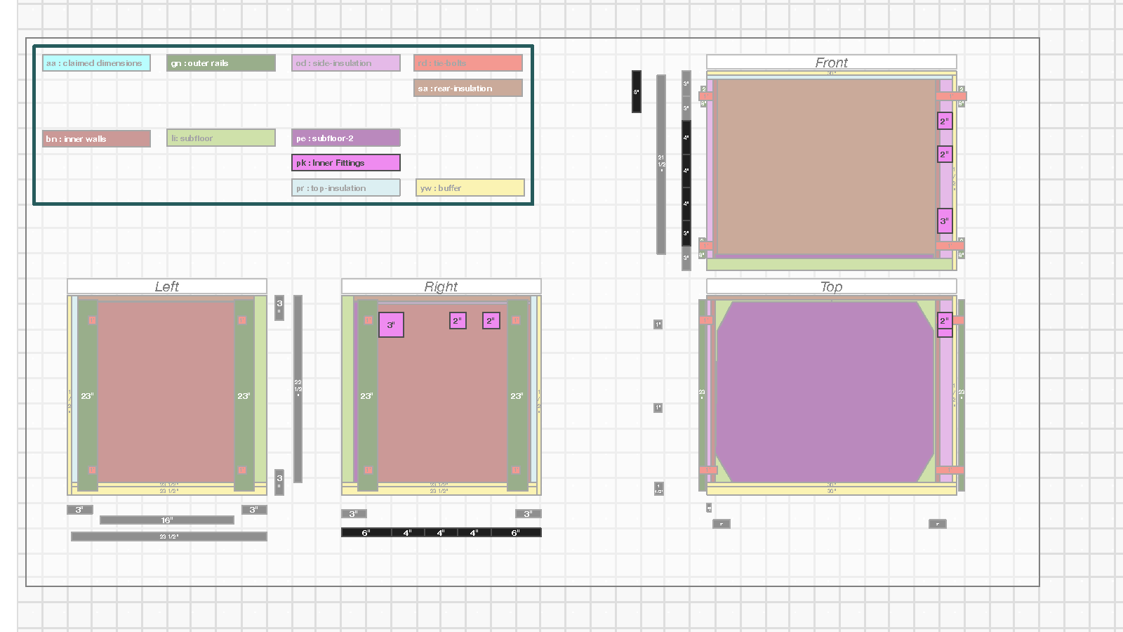
Penetrations
See: Vault-1 for diagram explanation.
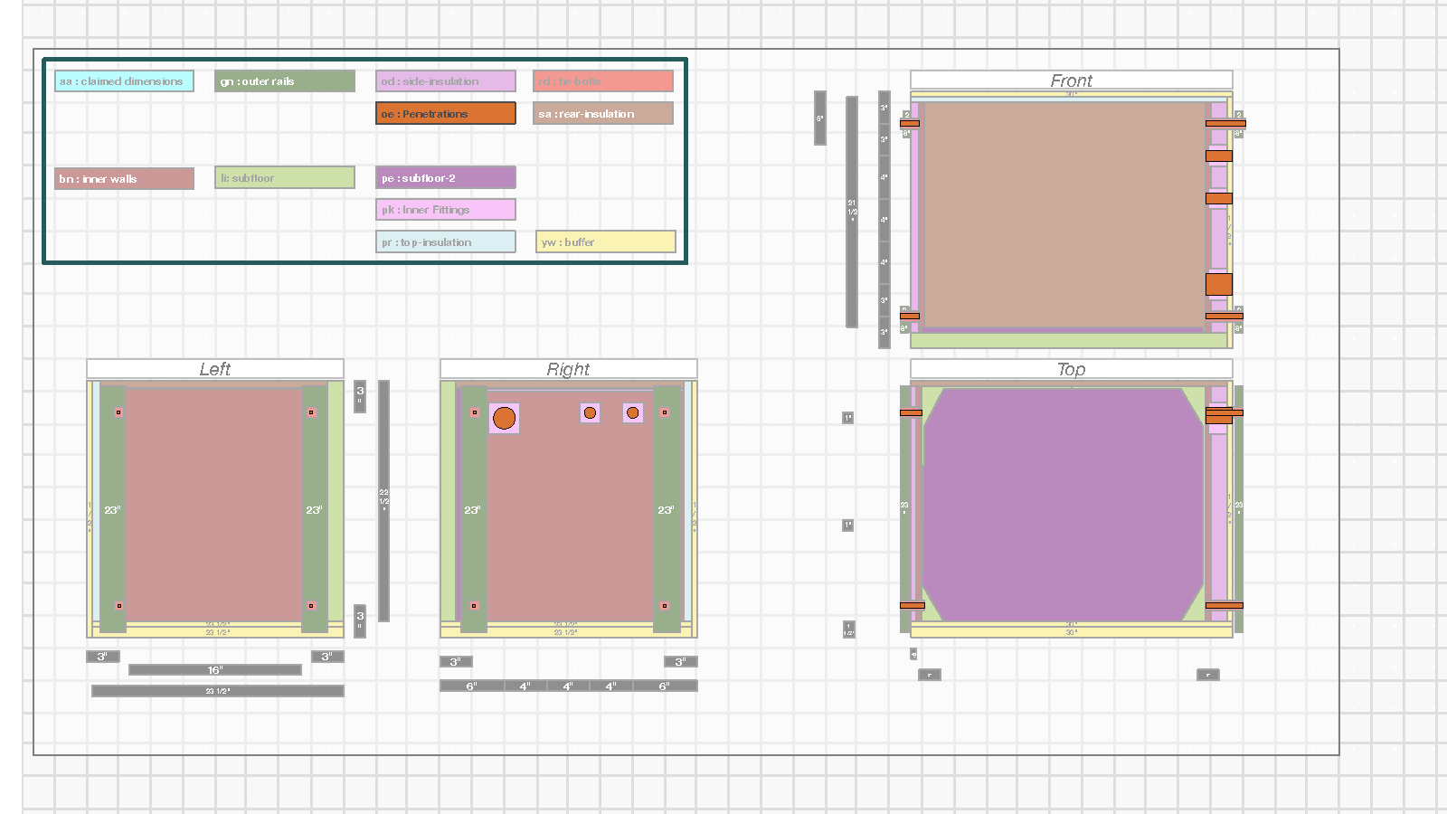
Additional Structures
The above section built a significantly sturdier box with attachment points on the inside and outside of the box, and with penetrations going through from the inside to the outside. This section describes the additional structures that are generally useful for a vault and present in Vault-2
Inner Shelving
The shelving for Vault-4 spans inward 8” from the right-hand (control) side of the box. With significantly more depth and height, but limited width, the shelves are stacked as much as possible while:
- Allowing enough height for components on the shelf
- Avoiding blocking access to the conduit
- Enabling wires to reach the conduits when mounting boards are placed on the shelf and when they are removed.
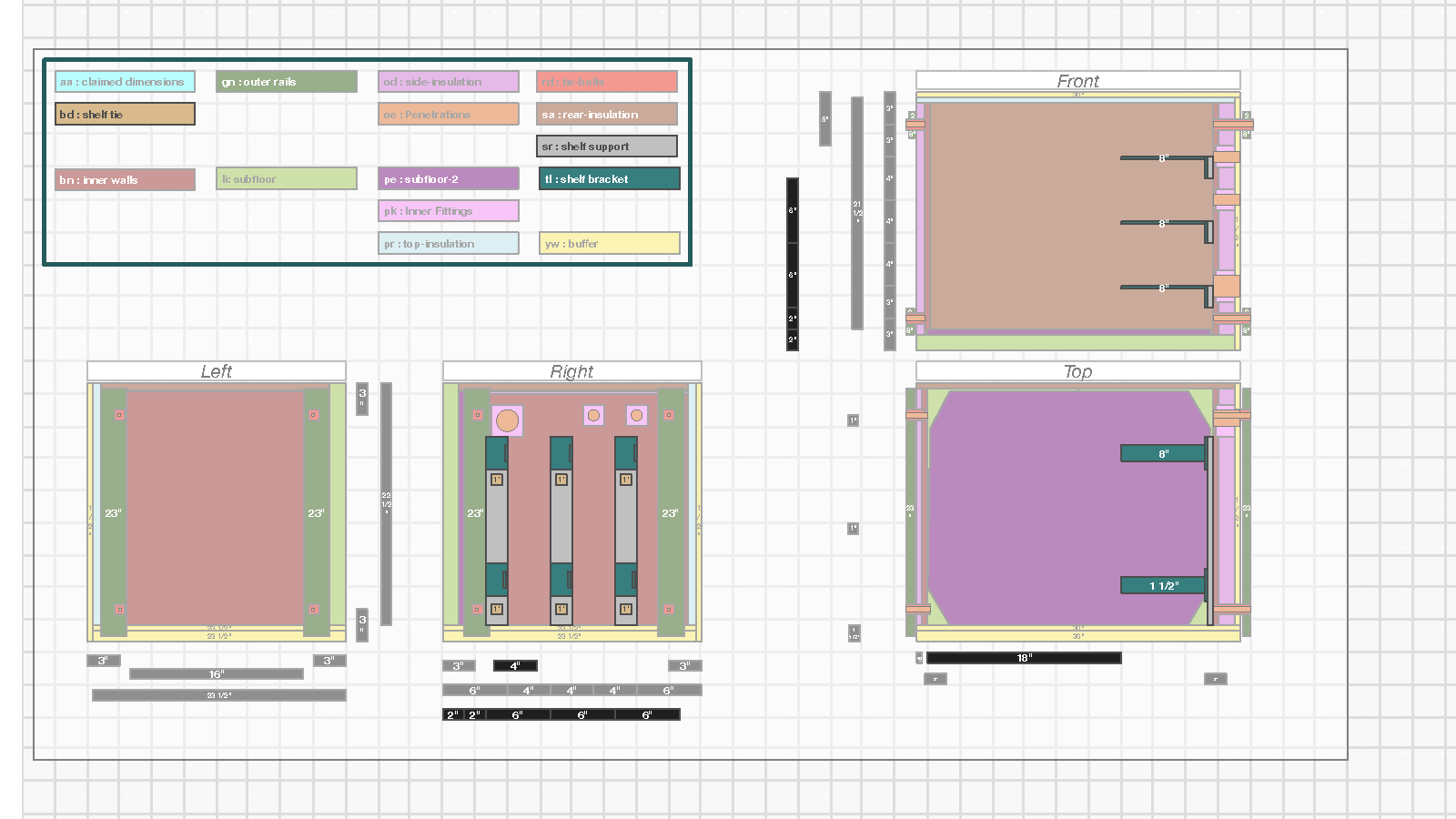
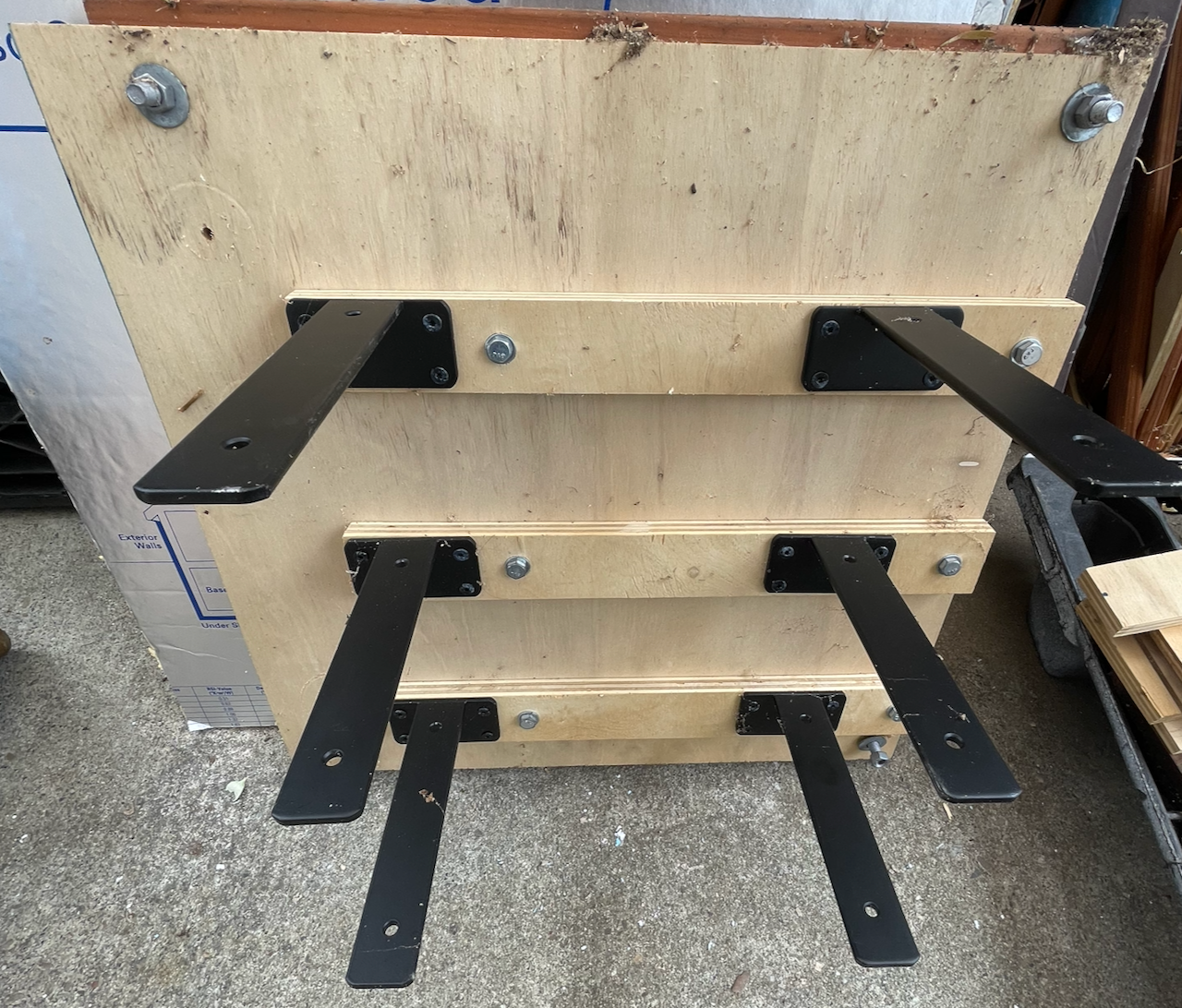
The following shows an example of the bracket and support design for Vault-4.
Mounting Shelves
For Vault-4 there is no additional structural shelf, so mounting boards are simply slid into place. The main issue is the boards need to have carve-outs in the back so conduit fixtures are unobstructed and wires can travel along the back.
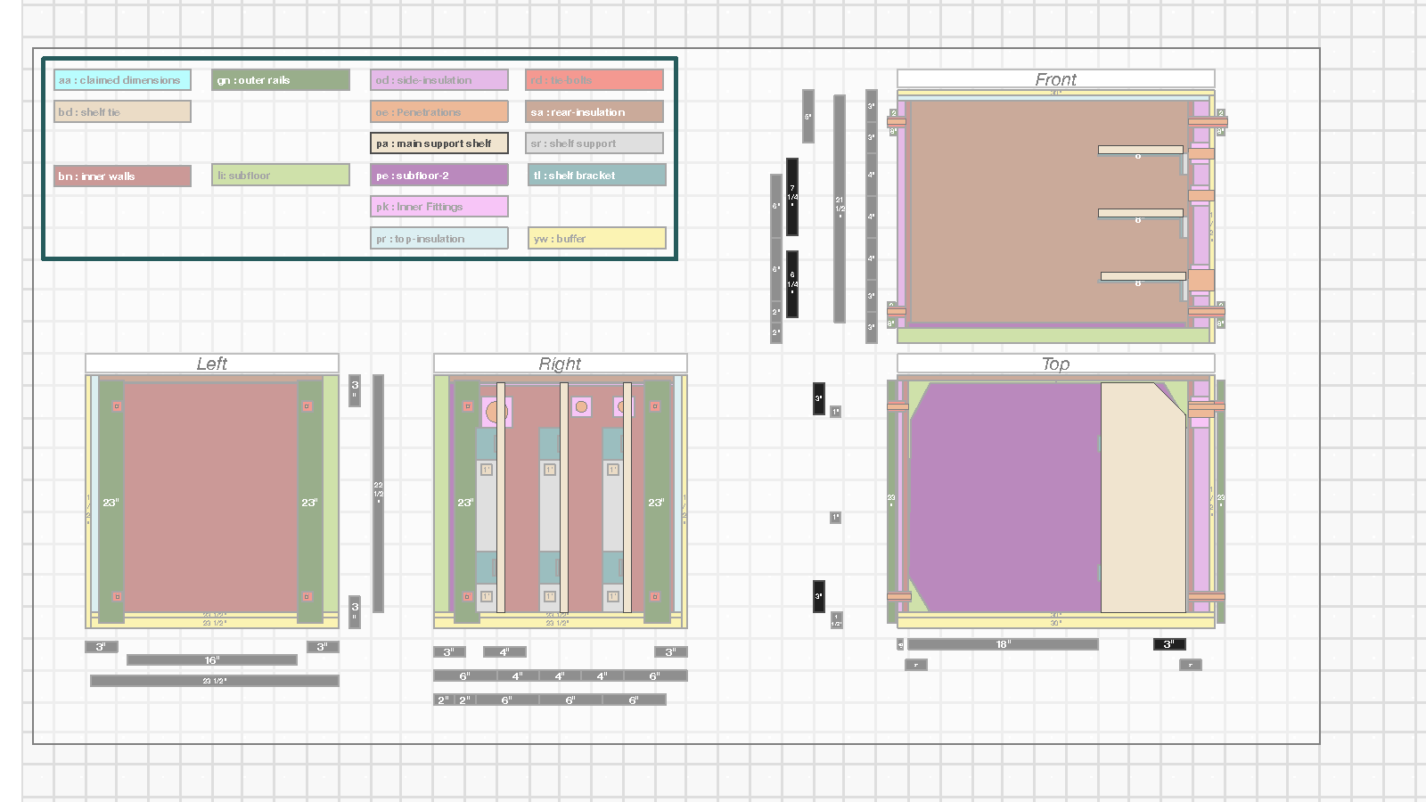
The following is an example of the shelves laid outside the shelving system:
Note that the wiring design for Vault-4 allows individual shelves to be accessed/removed (using some care) without disconnecting any wires: the conduit-destined wires are long enough to reach when the shelf is pulled out and the front wires have enough slack to handle a single shelf being pulled out from the others.
The front can look messy but this visual jumble is simply due to overlapping excess cable length and not tangling. It can be easily tied up, but there isn’t any particular functional advantage.
Outside Boxes
As can be seen in the picture, the outside electrical box is transparent and additional gang boxes run along the side of it. The transparency enables some visibility of status and the example box has a fair amount of space inside it.
Given this type of detail is both similar to Vault-1 and would be customized to the needs of the Vault, the schematics of the electrical boxes is not provided here.
Connecting to the outside is done in the same way as for Vault-1, with a junction box that is attached to two ¾” conduit hubs and provides a large surface to interconnect with the electrical box at appropriate locations.
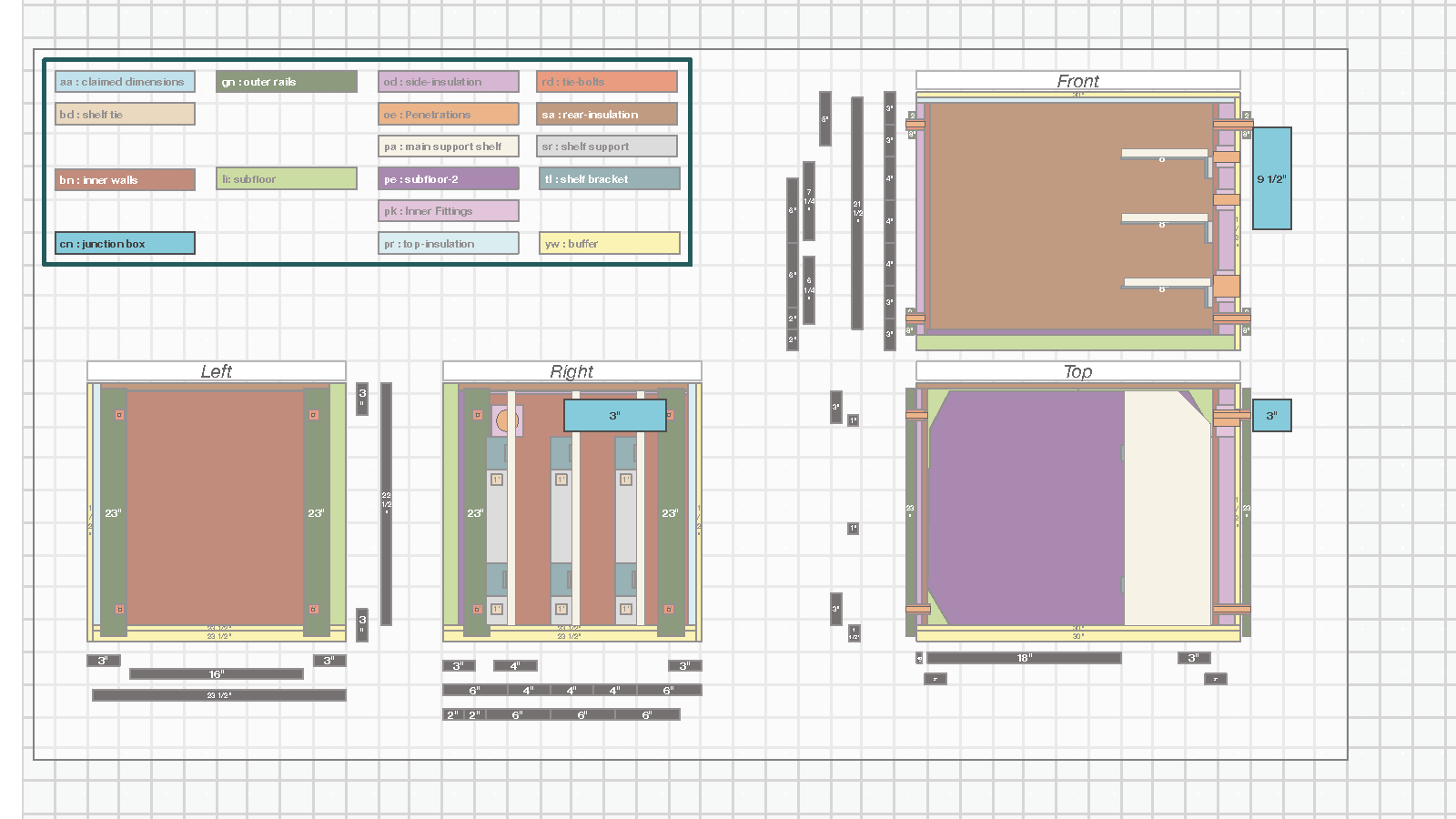
The final outside connection for Vault-4 is a 1.5” myers hub that is threaded into the conduit connecting to the inverter. For this diameter the conduit can support up to 4/0 conduit and over 300A (15kW) although Vault-4 only uses 2AWG for a bit more than 100A (5kW).
Summary