 kWhik
kWhikVault-1 (Gen-1)
A PowerVault is a weather-resistant chest that provides for safe electrical usage outside the confines of a sheltering building. Vault-1 is an all-in-one (Solar-In, Battery, DC-Out, AC-Out) storage and generation system that provides a good base description of the vault design concepts and their implementation. See PowerVault Gen-1 for details about PowerVault designs in general and Vault-4 for another kind of vault.
Vault-1 is a simple 12V system with a 1200W inverter, a 100Ah LiFePo4 battery, a 100/20 MPPT, several AC power outs, and several monitors and controls (DC shunt, AC energy meter/switch, temperature probes, system controller, etc.). This is all housed within or attached to the side of a water-resistant central toolbox.
Product Pictures
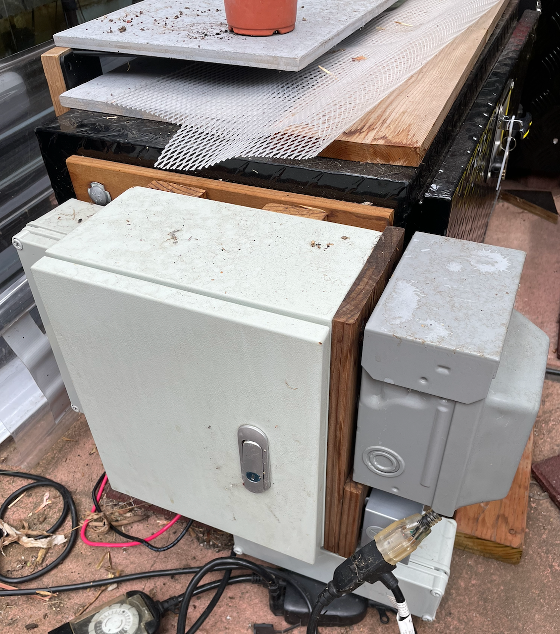
Some pictures are below: note that these are pictures of running systems, please excuse the mess :-)
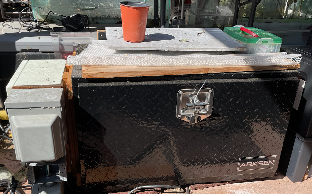
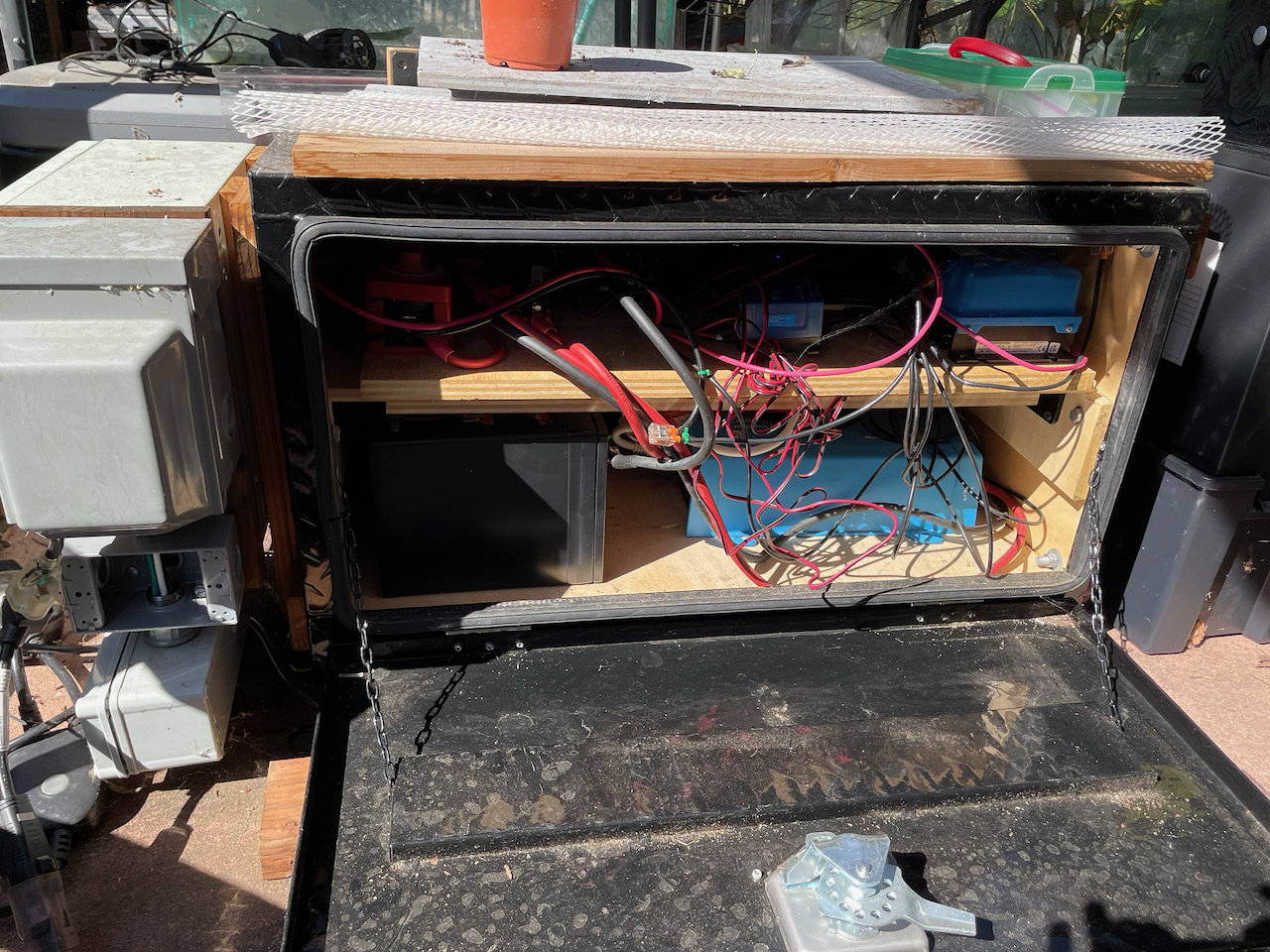
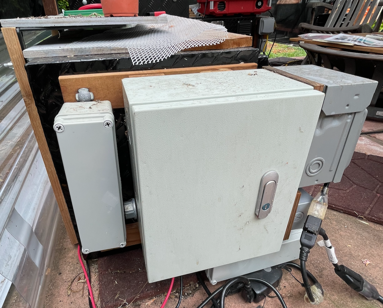
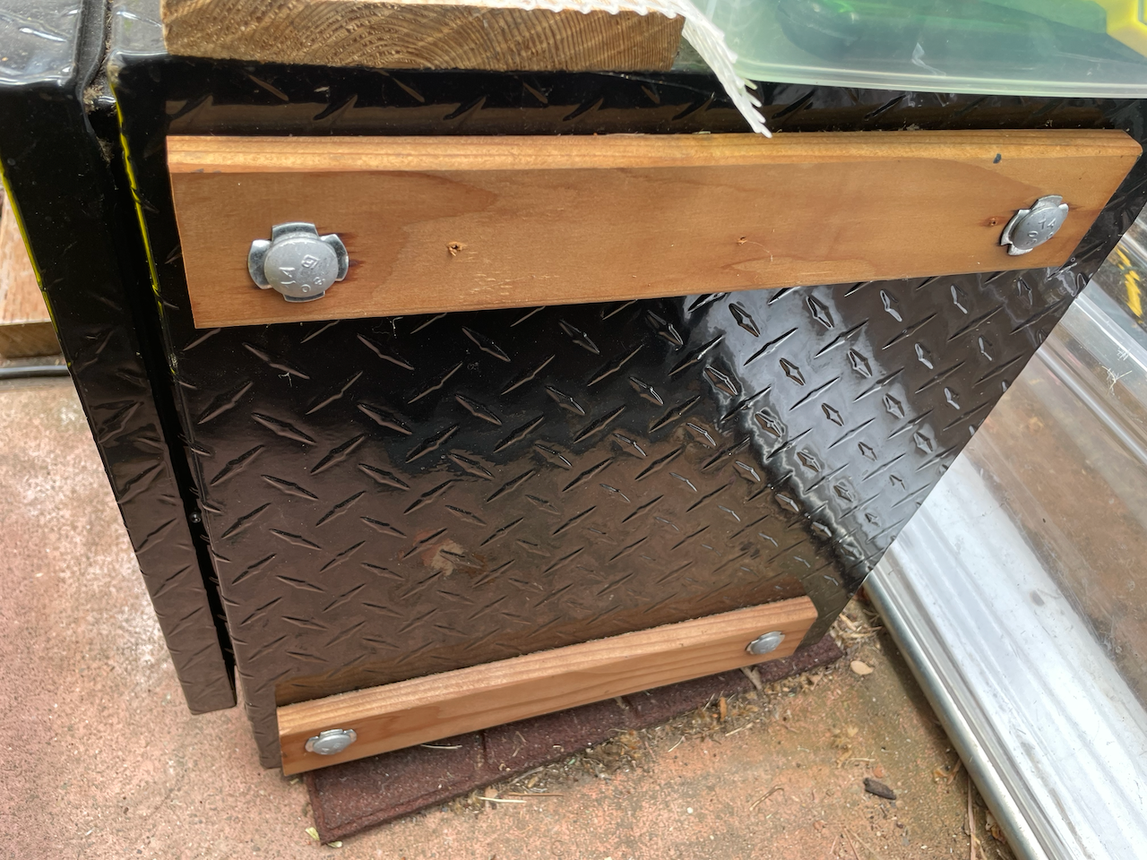
The following describes the details of building the vault and the design concepts that went into that build.
Table of Contents
Core Structural Aspects
A Vault is structurally based on truck “Tool Boxes”. Vault-1 is an aluminum 17”x18”x30” (depth-height-width) underbody toolbox and specifically this product: Arksen 192928026887
To transform the toolbox into a Vault we need to:
- Frame the inside
- Frame the outside
- Connect between the two
Framing the inside
Framing the inside involves:
- Providing a floor
- Providing walls for the inside structure: a single full-width shelf
- Providing support for the outside framing
The inside framing is done mostly with ½” plywood. Backerboard for the components is a separate aspect and is done with HexPly so the framing can focus on structural needs.
The subfloor is 1½” XPS topped with ½” plywood to raise the system base level up to the lower lip edge. Using XPS under the plywood provides a modest temperature and moisture barrier against the cold ground that the vault could be resting on and any condensation that might accumulate and drip downward.
The walls are ½” plywood to provide sufficient strength when sandwiched with the toolbox aluminum and the outside ‘rails’ (see below). On their own, the side walls do not have sufficient tear-out strength for hanging shelves, but when they are structurally laminated with ¾” plywood the total strength is more than enough to hold 100lbs (45 kgs) on a full-width shelf.
Framing the outside
The outside is framed with ‘rails’: either redwood or cedar planks that will be bolted with ⅜” bolts through the aluminum to the inside. The advantages of using rails are:
- Readily accessible and less-expensive weather-resistant materials
- Minimize penetrations required for fixtures
- The inside wall becomes the master stencil and pilot-hole jigs for the system, minimizing the chance of misalignment. A rail has only two holes, so it is easy to have each rail agree with the corresponding holes on the inside wall frame.
- Esthetically attractive and sturdy
Connecting the inside to the outside
The vault build uses stencils and jigs to have common positions pilot-drilled onto other pieces so alignments match. The core stenciling is done using the inner walls as the jigs: the inner walls have pilot holes that will be applied to the toolbox walls and the outer rails before the inner-wall-pilots are cannibalized to the proper dimensions for the inner wall penetrations themselves.
The most important aspect for this is to make sure the precision of the jig-pilots are appropriately sized for aligning and guiding the subsequent penetration drilling into the pieces. The pilot precisions include:
- Small: ⅛” ‘Narwhal’ pilots
- Medium: ¼” ‘Arbor’ pilots
‘Narwhal’ pilots are used for anything that needs a fairly precise pilot, especially Forstner bits. They are also used for sanity checks since having a misplaced ⅛” hole is easily rectified and commonly consumed by the final penetration hole.
‘Arbor’ pilots are the official pilots for the hole saws, which are used extensively for conduit fittings and providing space around the fitting.
The appropriate pilot bit is used with the inner-wall-as-jig to transfer the template onto the corresponding surface, and then that target surface is drilled to the penetration hole size using the pilot.
The Main Structural Build
The critical positioning to get right for all vault builds are the structural ⅜” tie-bolts going through the side walls. These need to be spaced from the edge and projections/penetrations to prevent collisions and be structurally robust. The internal obstacles include the floor, any insulation, shelving locations, and penetration fittings. And as mentions, the bolts must have sufficient edge distance on the inner framing wall and outer rails for both grip and material strength.
Beside the structural importance of the tie-bolts for the finished build, the bolts also are used to align the pilots between the inner-wall-as-jig and the toolbox sides. As soon as two corners are locked into place by the tie-bolts, all other pilots are positioned precisely between the two surfaces.
Historic Template
Combining the above positioning with build tolerances give the following example wall-template jig for the ‘electrical box’ side of a 17x18 [this is just an old example… schematic for a real version to follow].
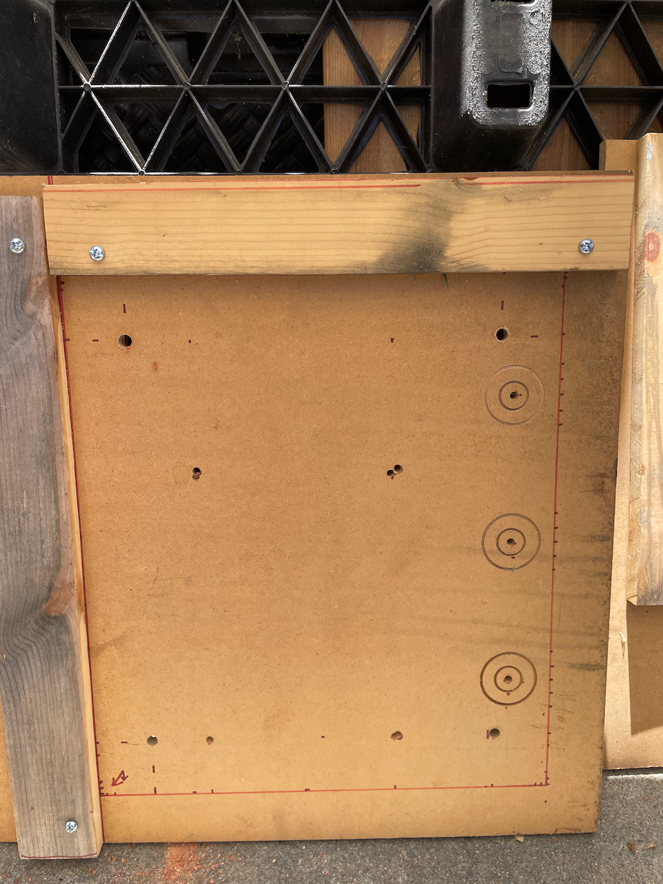
Ringed holes are for penetrations and fittings. Other holes are for structural use including the four corner ⅜” tie-bolts. This earlier generation of template uses ¼” pilots only but that caused issues with Forstner and similar precision bits.
Ultimate Schematic
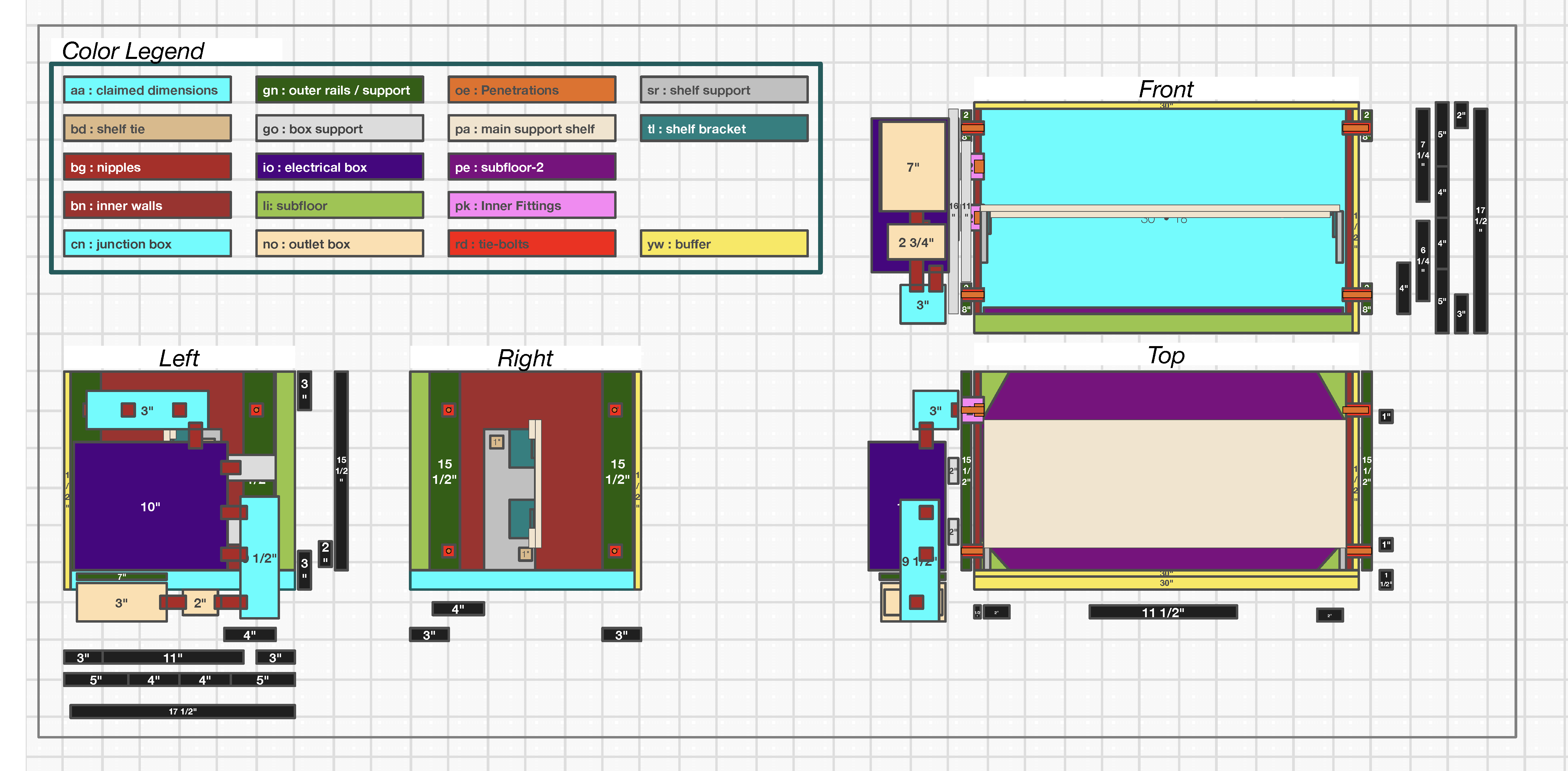
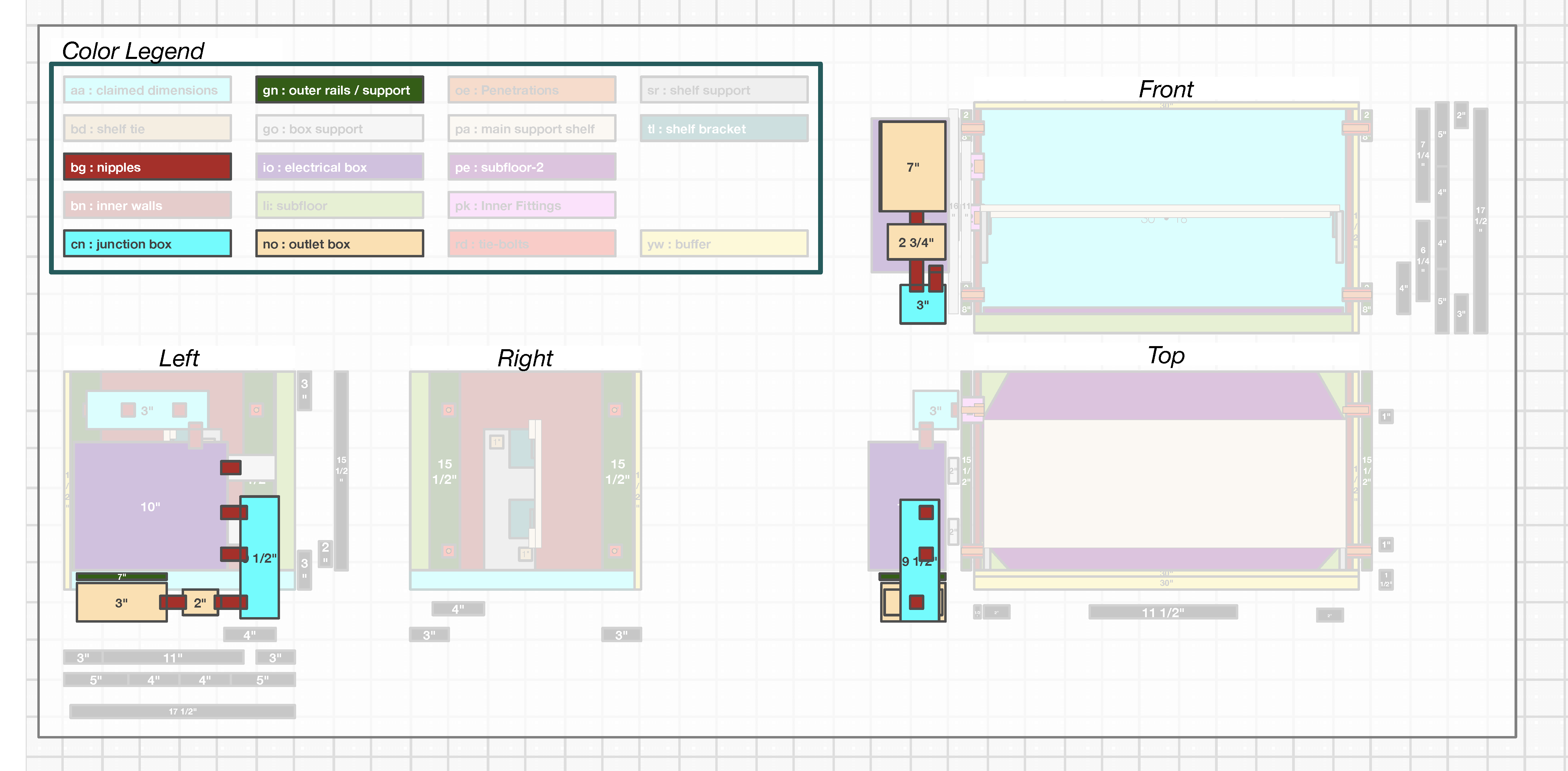
Getting a bit ahead, the following is the current generation schematic for the complete Vault-1. This will be explained in the subsequent sections.
Base toolbox dimensions
The 17x18x30 toolbox has a ‘neck’ to enable sealing the front door and the dimensions provided are for the outside of the box. To handle these aspects and provide tolerance for fitting pieces, a half inch of clearance space is provided on the top, a side (shown as ‘right’ but really shared by both sides), and the front. An additional inch of space is removed from the front to account for the neck. So the inside dimensions are 15.5” deep, 17.5” high, and 29.5” wide.
The following diagram shows the views of the box from the left, right, front (to back), and top (to bottom). Aqua (‘aa’) represents the claimed dimensions and Yellow (‘yw’) are the buffer spaces.
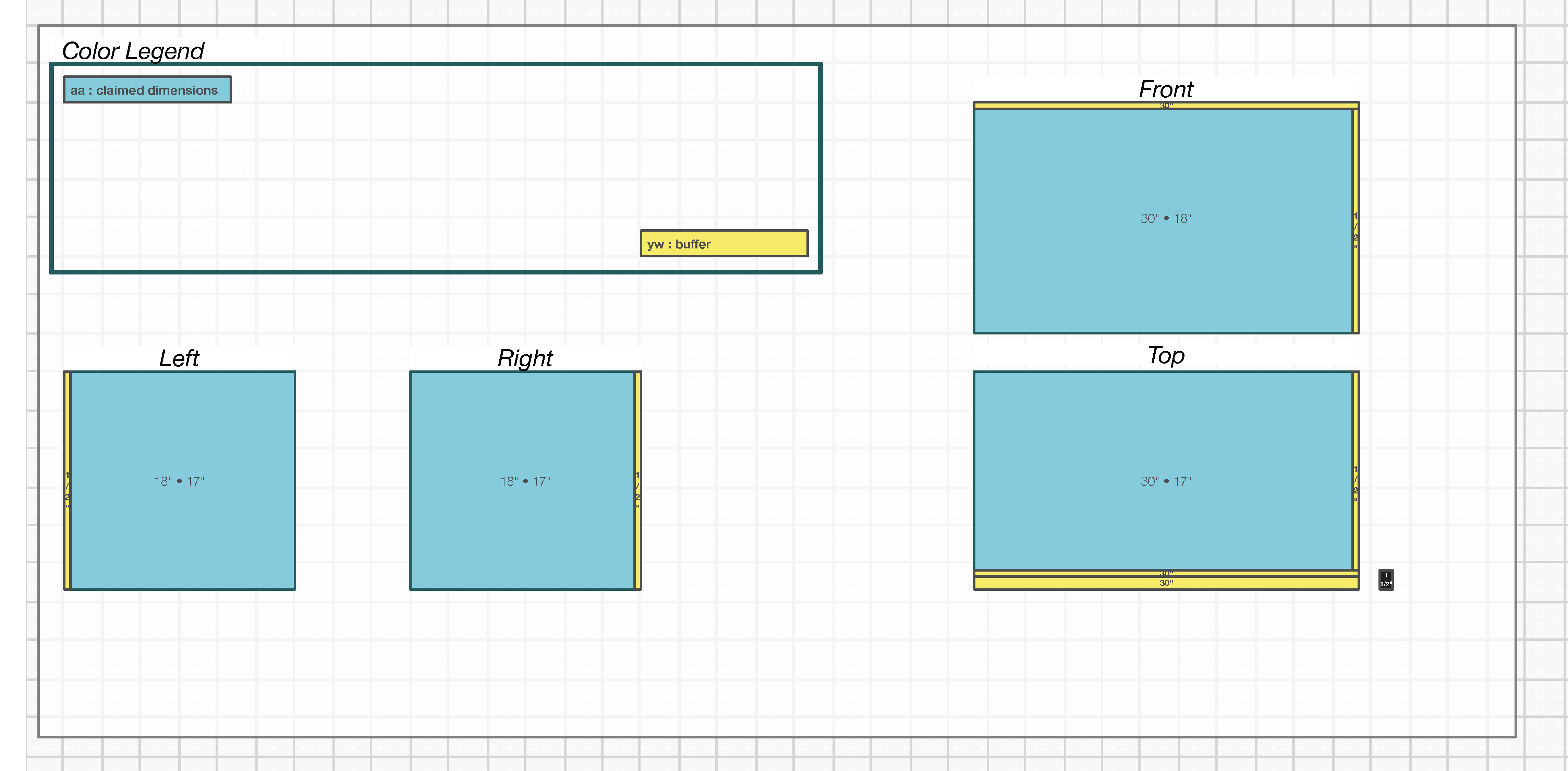
The ‘Color Legend’ will be filled in as the build progresses, and see Ordinary Colors for details on the color system if interested.
Subfloors and Inner Walls
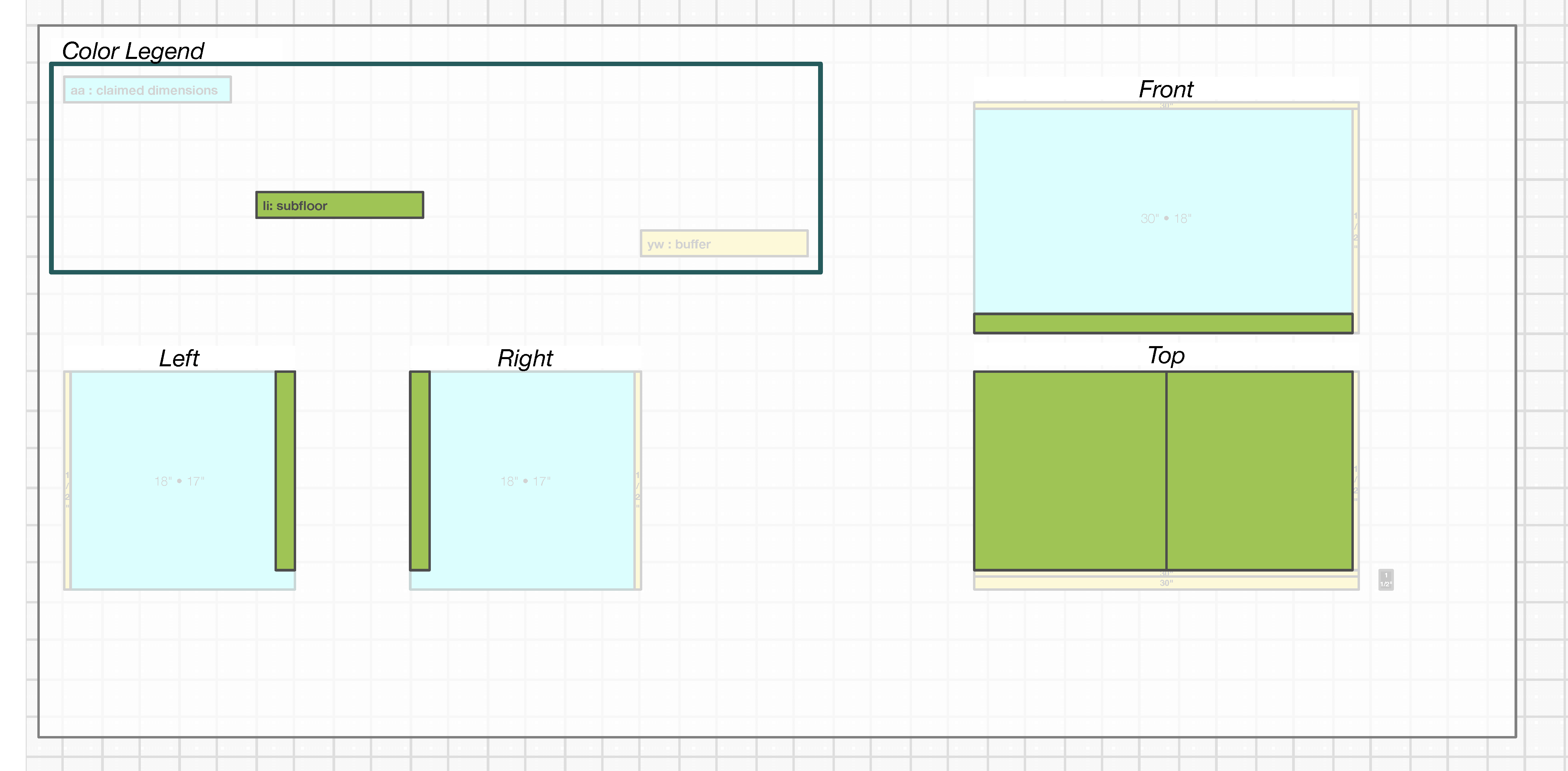
A subfloor of 1.5” XPS is used to provide some amount of insulation from the ground and also to lift the functional floor up to the height of the neck (about 2” up). Vault-1 has no serious insulation, but this subfloor will be an integral part of insulating Vault-4 and similar vaults with significant thermal resistance.
The following shows the subfloor in lime (‘li’) spanning the whole bottom as two pieces (side-to-side). Dividing it into two pieces enables fitting it through the neck and laying it down more easily. The XPS will also compress to fit, making the placement easier in spite of the 1.5” thickness.
Inner Walls
The side inner walls shown in brown (‘bn’) are fastened to the toolbox side walls. They are sized to fit on top of the first subfloor without gaps. This relationship is part of the insulation model where the side insulation will match the dimensions of the side inner walls, providing a continuous insulation box and minimal thermal bridging. The side walls hold the continuous insulation pieces into position.
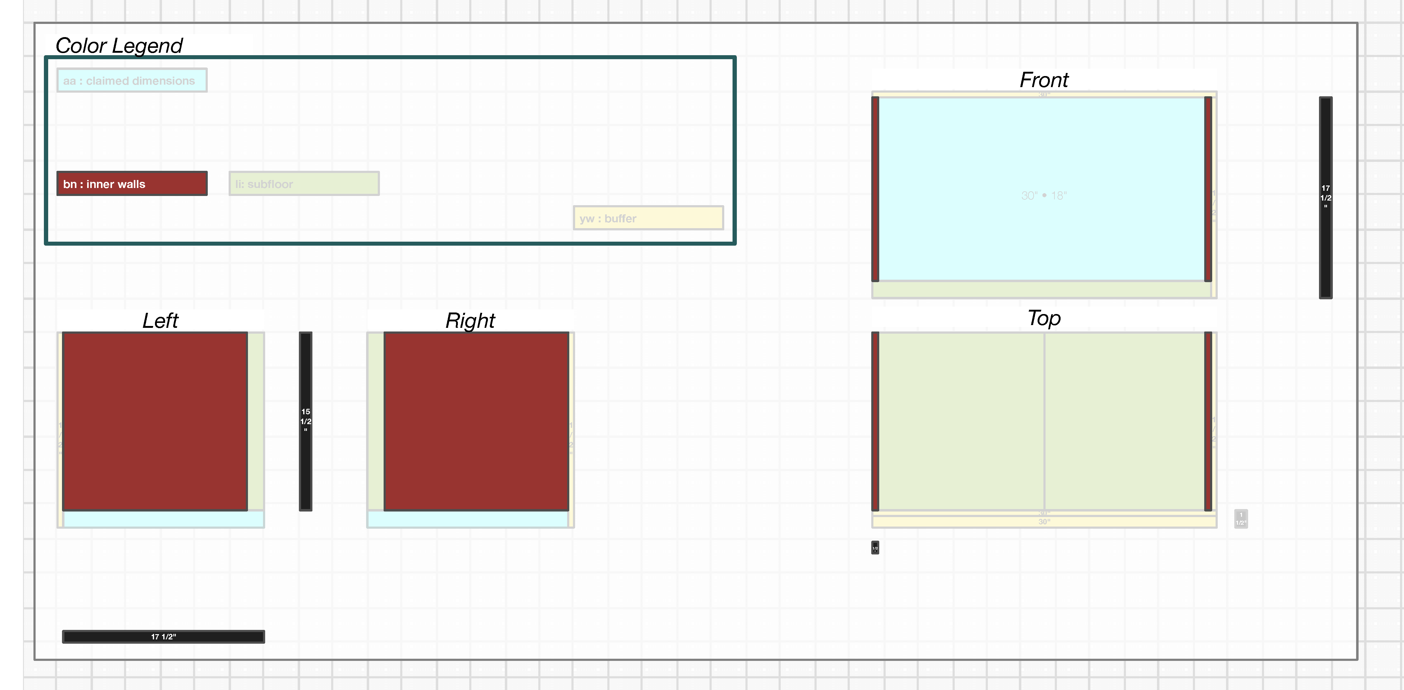
The inner walls are only ½” thick, but they are secured against the aluminum side walls with rails on the opposing side, so their structural strength is considerably stronger than the ½” thickness would indicate. But in acknowledgement of their limited pull-out and shear strength for fasteners, inner shelves are not attached directly to the ½” inner walls. Instead, any load fasteners are attached to ¾” plywood that is ‘laminated’ by bolts to the ½” inch inner walls.
The thickness of the inner wall is optimized to enable side-wall insulation to be present without the functional inner dimensions being overly reduced. This is especially critical for Vault-4 where 18” of inner space is taken up by three rack batteries and additional space is taken up by the continuous insulation spanning the sides.
Subfloor-2
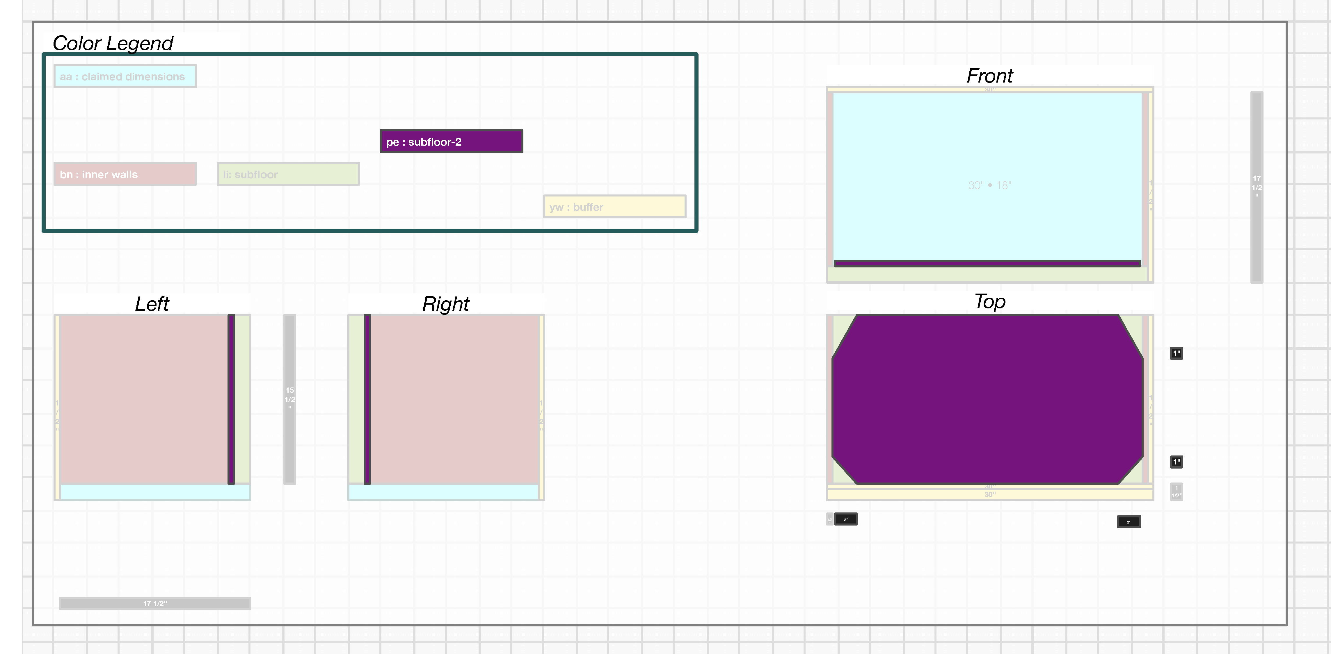
The second subfloor shown in purple (‘pe’) is ½” plywood and sits on top of the XPS subfloor and inside the inner walls. It is a square sheet with carve-outs in the corners that are to make sure the tie-bolt nuts and washers are unhindered and easily accessible. The carve-outs are small enough that they do not diminish the supported space of the floor (either bare equipment or backerboards).
Outer Rails and Tie-Bolts
The outside of the vault uses horizontal rails shown in green (‘gn’) made of ⪆2” wide by ⪆½” thick redwood or cedar boards that span the same depth as the inner walls.
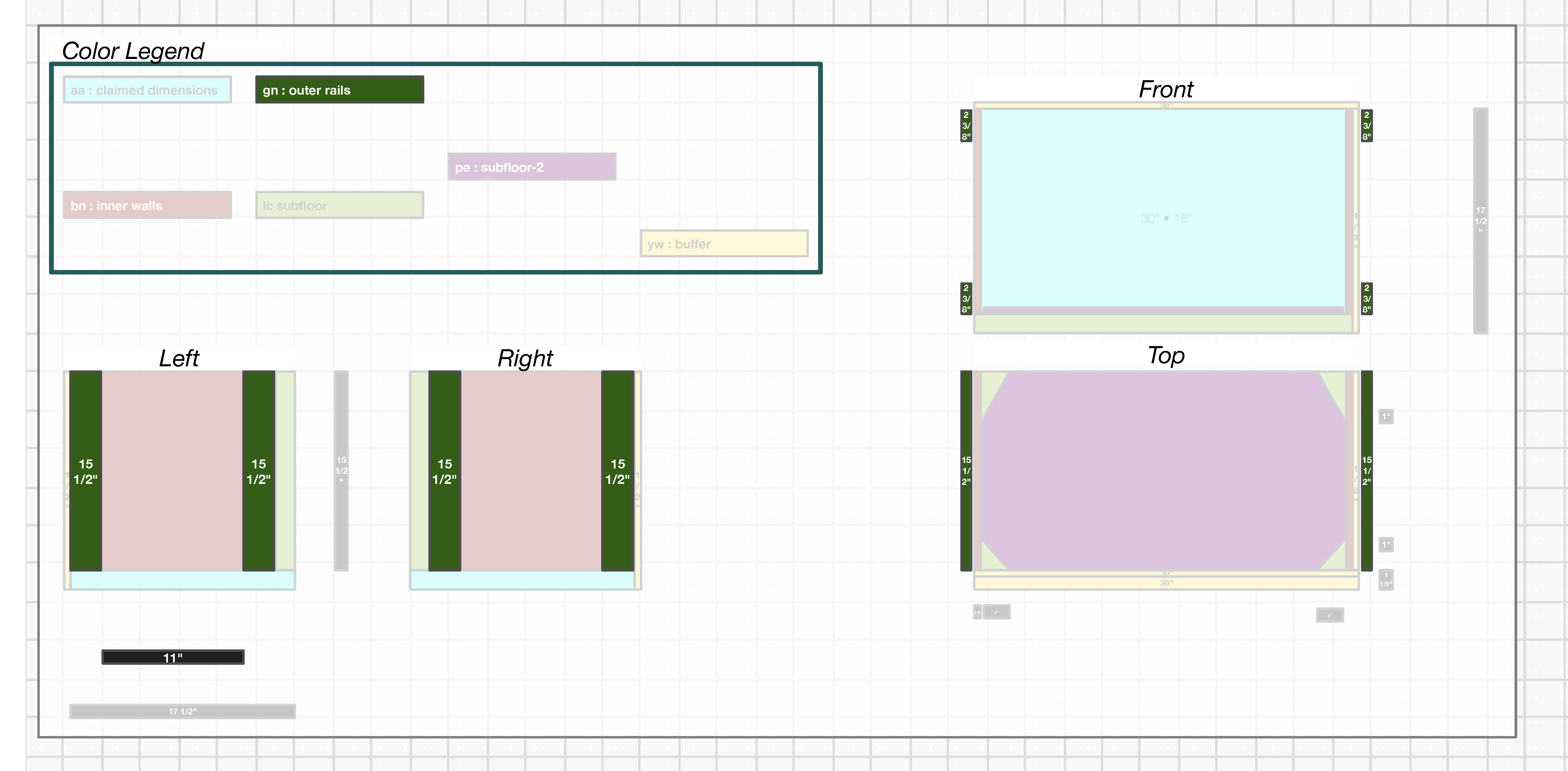
The extra width is given to the outside (top or bottom) so the middle section has a well-defined distance between the rails of 11” and also to provide enough clearance for the fixtures (e.g. Myers hubs) connecting to the inside.
The following shows the rails on the right (non-electrical box) side.
Tie-Bolts
The Tie-Bolts shown in red (‘rd’) connect the outside rails to the inside walls, sandwiching the toolbox aluminum wall between them. These are positioned 3” from each edge except the top edge which is optimized to just 2” for maximum space inside and out. This positioning:
- Avoids internal obstacles like flooring and insulation
- Provides a guide-line that other penetrations can align with
- Makes sure the structural strength (e.g. pull-out or pull-through) is sufficient for both bolts and washers
- Helps align the spacing of other penetrations and the electrical box
It is possible to tweak these numbers as needed given the clearance for the ⅜” bolts don’t need to be this large, but it produces esoteric variations that won’t work with other builds (especially Vault-4 that has very tight constraints).
Note that the shown tie-bolt blocks include space for heads, nuts, and washers and are not the bolt clearance diameter (see Penetrations below).
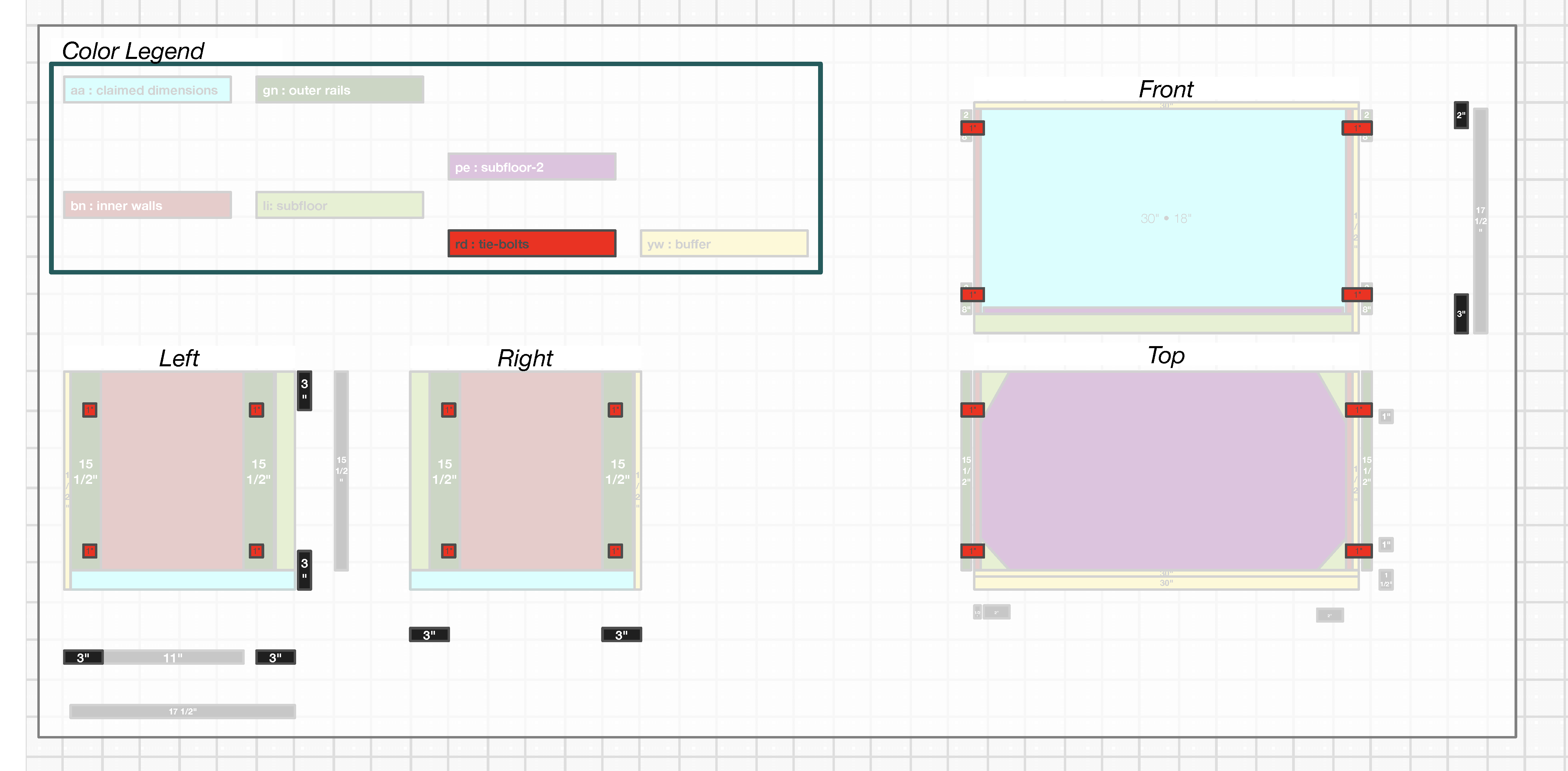
As can be seen with this last diagram, the Subfloor-2 and the Tie-Bolts could potentially collide if Subfloor-2 did not have the carve-outs (there is just enough space but only a ½” tolerance and no ability to use thicker XPS or plywood if desired).
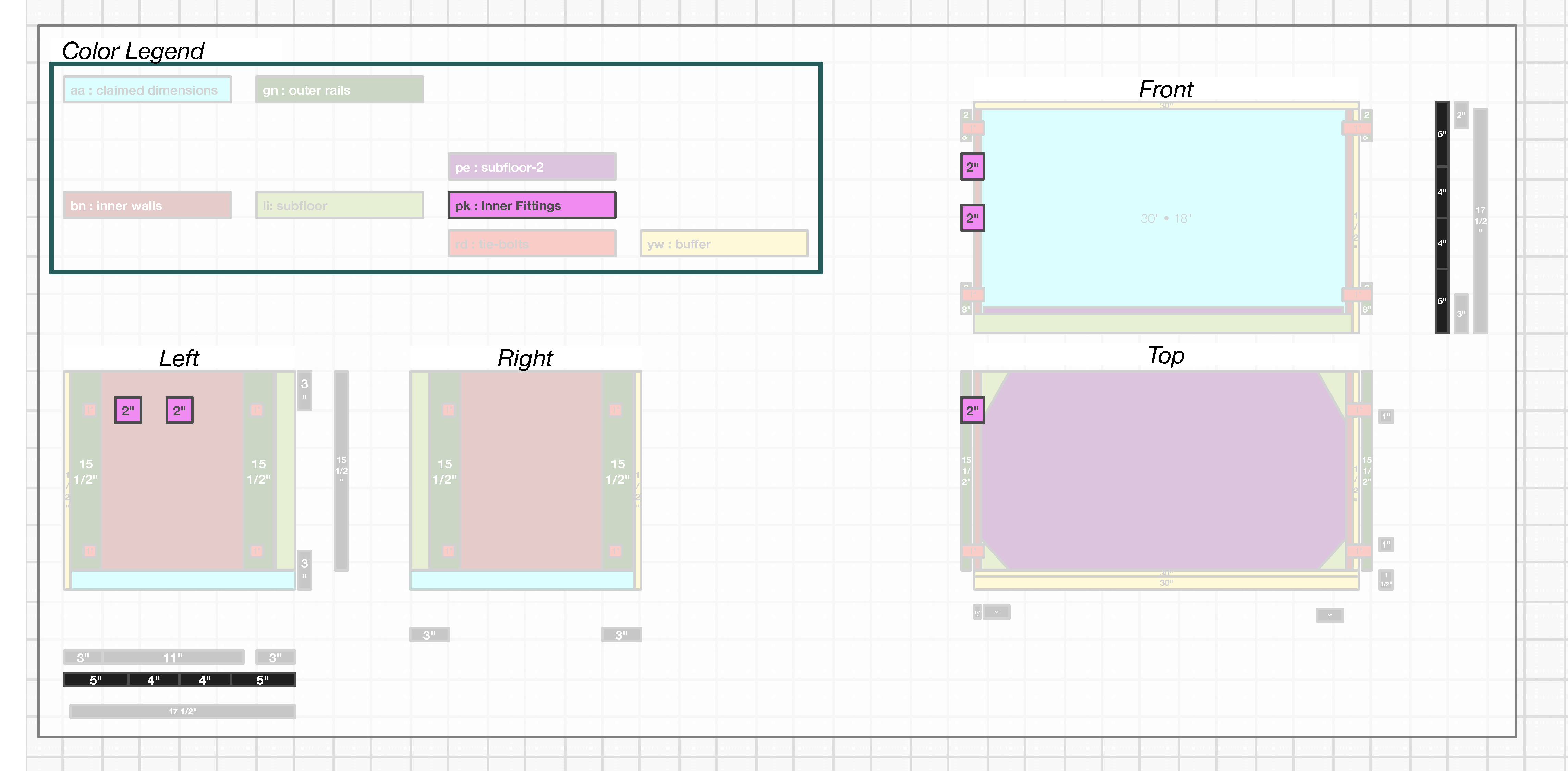
Inner Fittings and Penetrations
The Inner Fittings (e.g. Myers Hubs) shown in pink (‘pk’) span from outside the vault through the inner wall. The dimensions of these are for ¾” conduit for Vault-1, but the fittings have multiple dimensions to support the penetration through the toolbox and the necessary space for access to the nut on the inside wall.
Fortunately by using rails on the outside with sufficient clearance, the rails are not involved. And by using the inner wall as the main template, as soon as it is in place, the toolbox wall is piloted with the corresponding hole location and the main complexity is swapping drill bits for different materials and penetration dimensions.
Penetrations
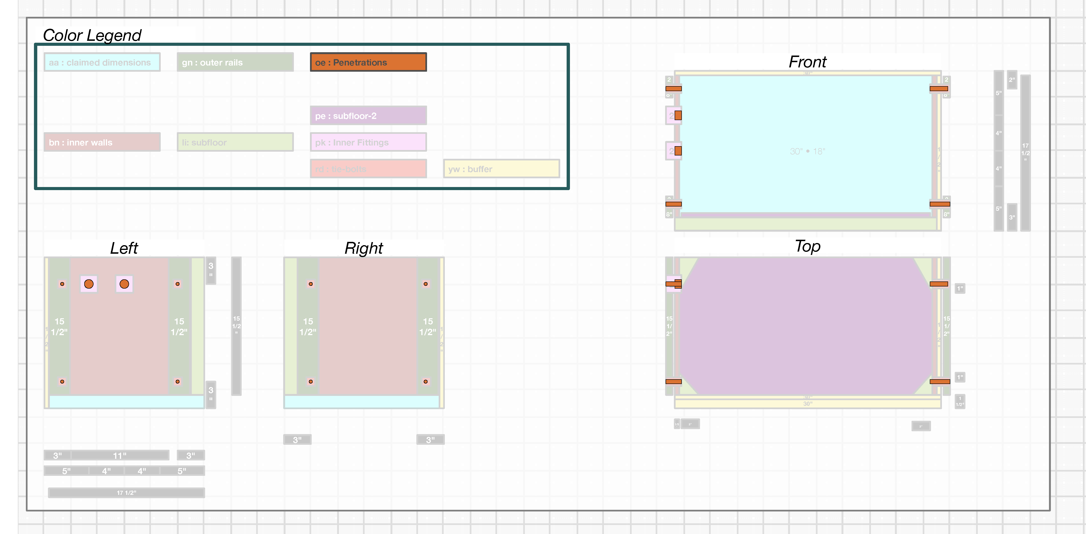
The actual penetrations required for the tie-bolts and fittings are shown in orange (‘oe’) and should be made to allow the bolt or fitting to cleanly enter the holes with sufficient clearance that alignment is not difficult and excess gaps are not present. For the ⅜” bolt, using 25/64” or 13/32” holes is recommended. The fittings require ~1/16” space around the outside of the penetrating portion.
The tie-bolts should be providing no shearing force directly and alignment does not need to be precise for shelving and hanging on the inside and outside. The tie-bolts are just used to compress the rail to the inner wall, which provides a very large area (many square inches) of friction to prevent sliding. The vault is also not meant to be lifted by the side rails, but instead by straps, pallet, or other support beneath it.
Additional Structures
The above section built a significantly sturdier box with attachment points on the inside and outside of the box, and with penetrations going through from the inside to the outside. This section describes the additional structures that are generally useful for a vault and present in Vault-1.
Inner Shelving
There are two major types of shelving inside the different styles of vaults:
- Complete Spans that go from side to side
- Partial Spans that extend out from a single side
Vault-1 uses a complete-span shelf so it is supported on both sides and is correspondingly fairly strong. The shelf support is designed to not rely on fixing the cross-members, so brackets extending from the sides go a significant distance to minimize the unsupported span.
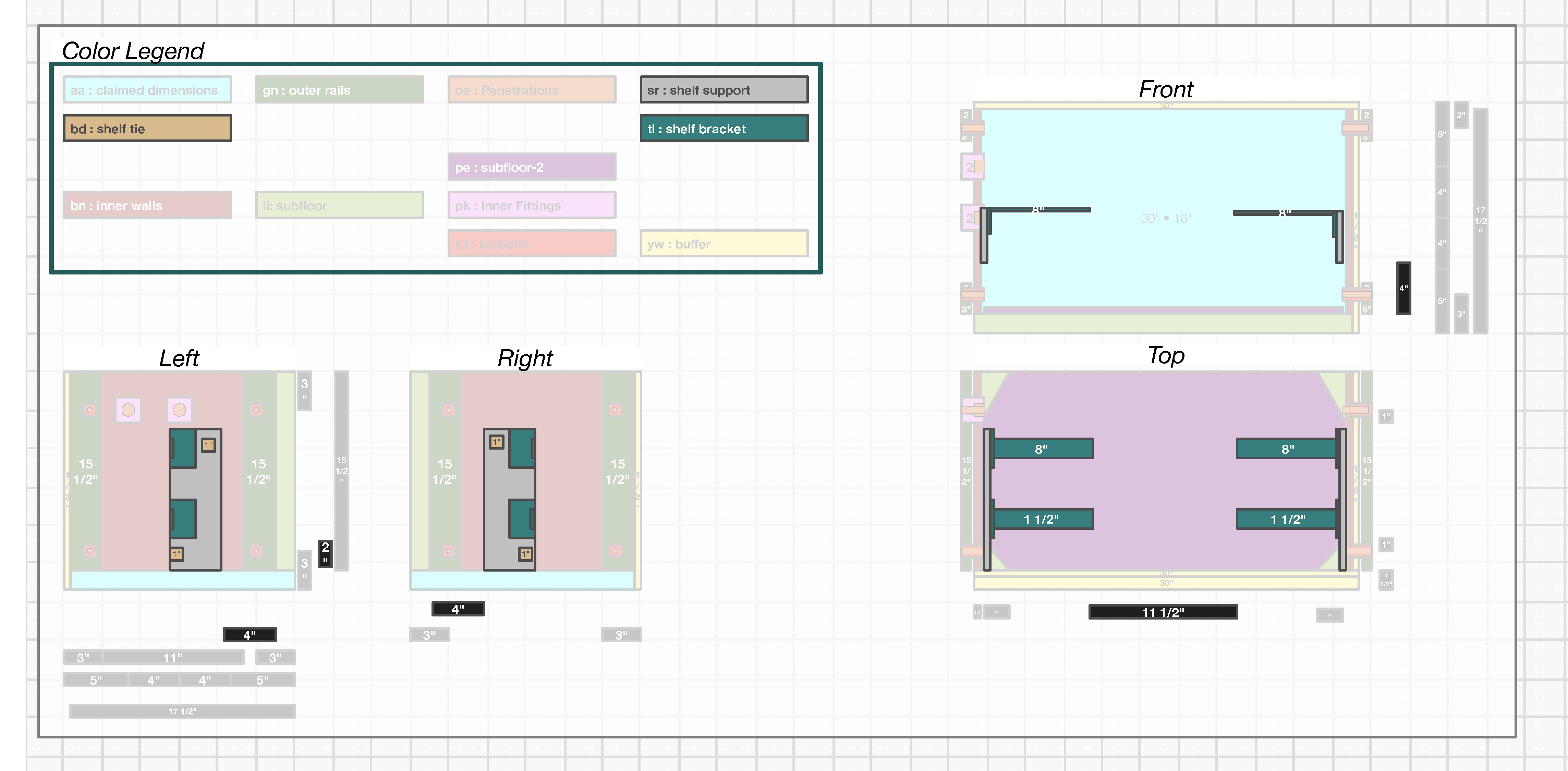
As mentioned above, shelf brackets are not directly attached to the inner walls. Instead, shelf brackets shown in teal (‘tl’) are attached to ¾” support plywood shown in silver (‘sr’) using appropriate screws. These shelf brackets are then mechanically laminated to the inner walls with ¼” T-nuts and bolts shown in burlywood (‘bd’). Besides space optimization and structural strength advantages, this means the shelf supports can be added (and removed) after the inner walls are put in place. They can even be tilted so larger components can be slid into the top section at an angle and avoid the top of the neck.
The main shelf support mechanism are two 8” deep ‘hidden’ brackets that are attached to each ¾” support board. With these, the remaining span is less than a foot.
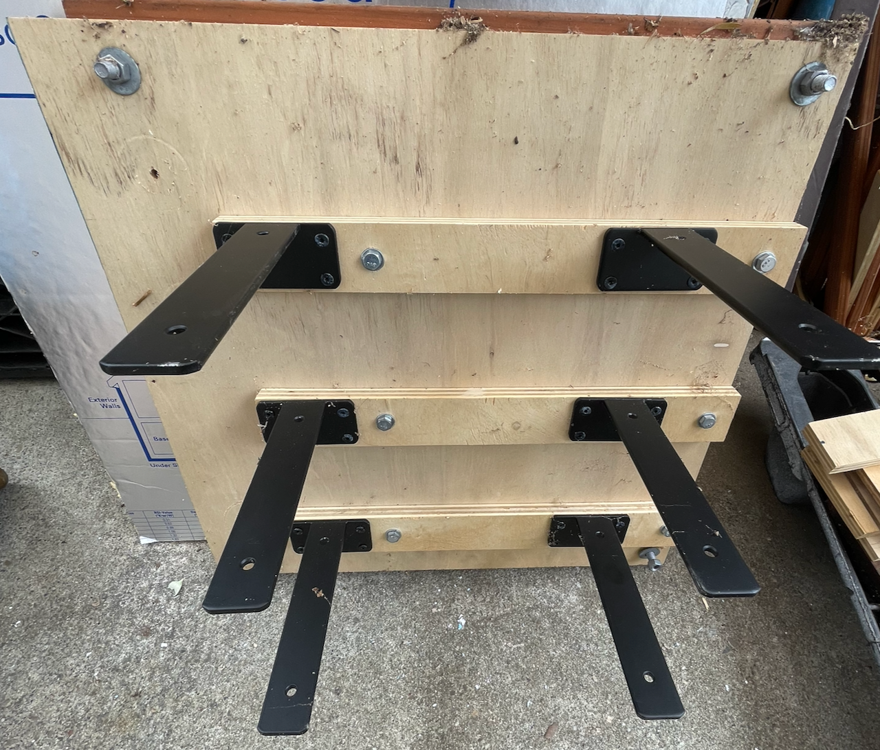
The following shows an example of the bracket and support for Vault-4. This is structurally a little different because there is more depth available and height is much more restricted, but the concept is the same.
Support Shelf
On top of the brackets a ½” full-width but only 3/4 depth shelf is laminated to two ½” full-width edge-boards that trap the brackets between them and is shown in buttercream (‘bm’). This shelf is 1” thick on the front and back edges and ½” thick in the middle with the metal brackets supporting them for 18” of the <30” width, or an actual span of only 12” where the edges are reinforced. On the whole, the shelf should functionally be capable of the 100lb (45kg) rating of the brackets, which is well above the weight of anything placed on the shelf.
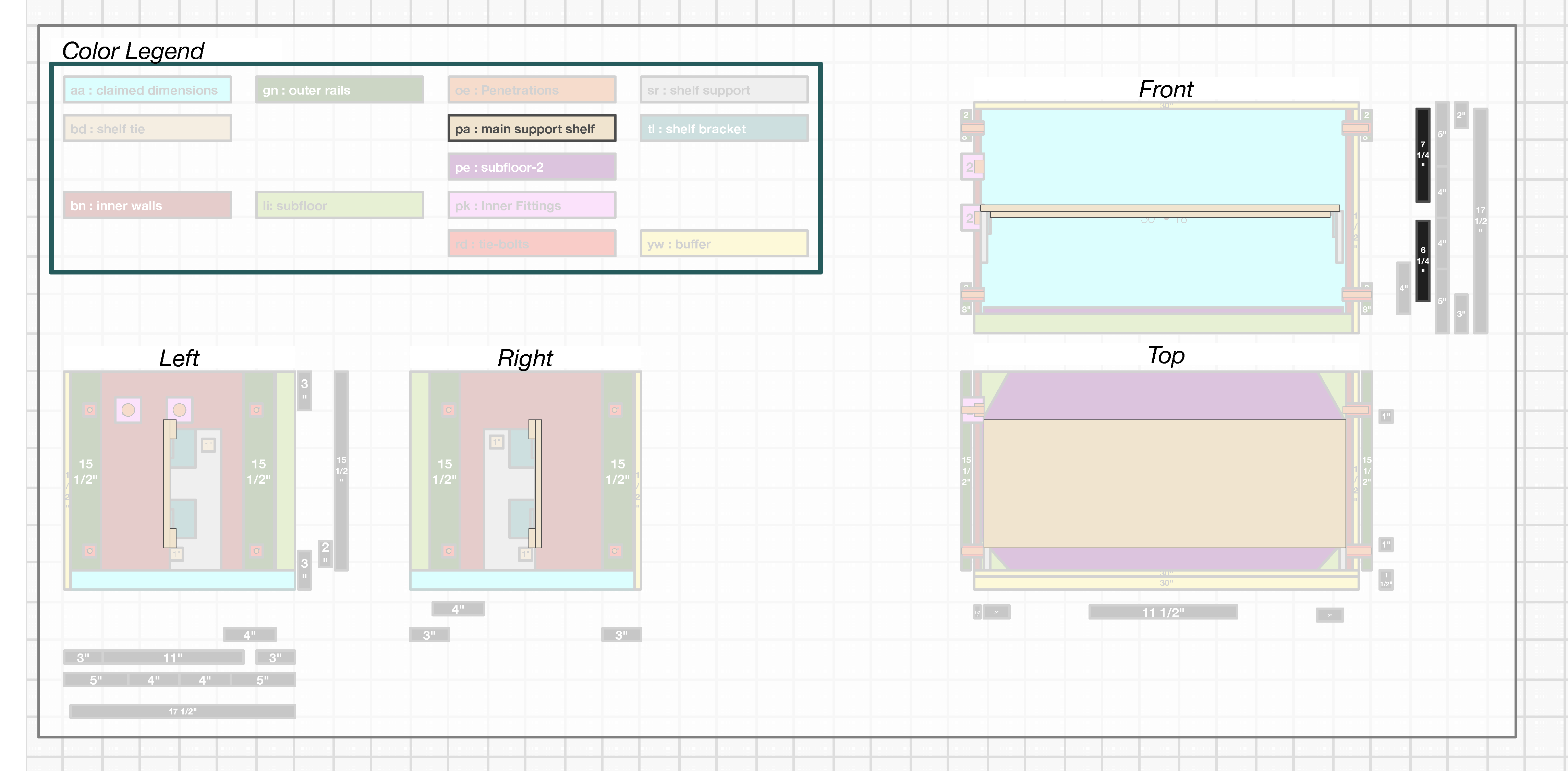
The shelf can be positioned higher or lower but clearance needs to be provided for the lower penetration fixture if it is being used. With the shelf in the position shown, the upper section has about 7” of height available except some of that height is occluded by the upper neck. The lower section is about 6” in height.
To access more of the upper section, you can see that the bolts attaching the shelf-brackets support are below the shelf and accessible when the shelf is laden. If the rear bolt is attached but not fully tightened, the laden shelf can be rotated up and the front bolt added. This allows the occluded section to be better utilized, making the upper section realistically more like 6” with the remaining space being for air movement.
Outer Circuit Box and Conduit
The outside of the vault provides circuit boxes, controls, outlets, and conduit connections. Vault-1 has the following outside aspects:
- Connections to the inside through two ¾” metal conduits
- A breaker box with both solar/dc and ac breakers in it, as well as being a conduit hub
- A four-way AC outlet box
- A 1-gang junction box for AC in if desired (not currently used)
- Conduit connection to solar/dc input
To create water-tight and flexible interconnections between these different boxes, the following are primarily used:
- waterproof junction boxes,
- rigid watertight hubs,
- chase nipples,
- other NPT threaded connections
beyond this core set for interconnections, the junction boxes can also have rain tight emt or other (NM, PVC) connectors to transition to external conduit. For Vault-1 the external conduit is EMT and goes to Vault-4 for 48V DC in.
Getting to the outside of the Vault
The two ¾” penetrations to the vault are threaded watertight hubs, so they can simply be attached with chase nipples into a waterproof junction box. Using a 250x80x85mm (9.8x3.1.x3.3 inch) IP67 Junction box shown in cyan (‘cn’) and chase nipples shown in bug (‘bg’) we can attach the junction box to the side of the vault.
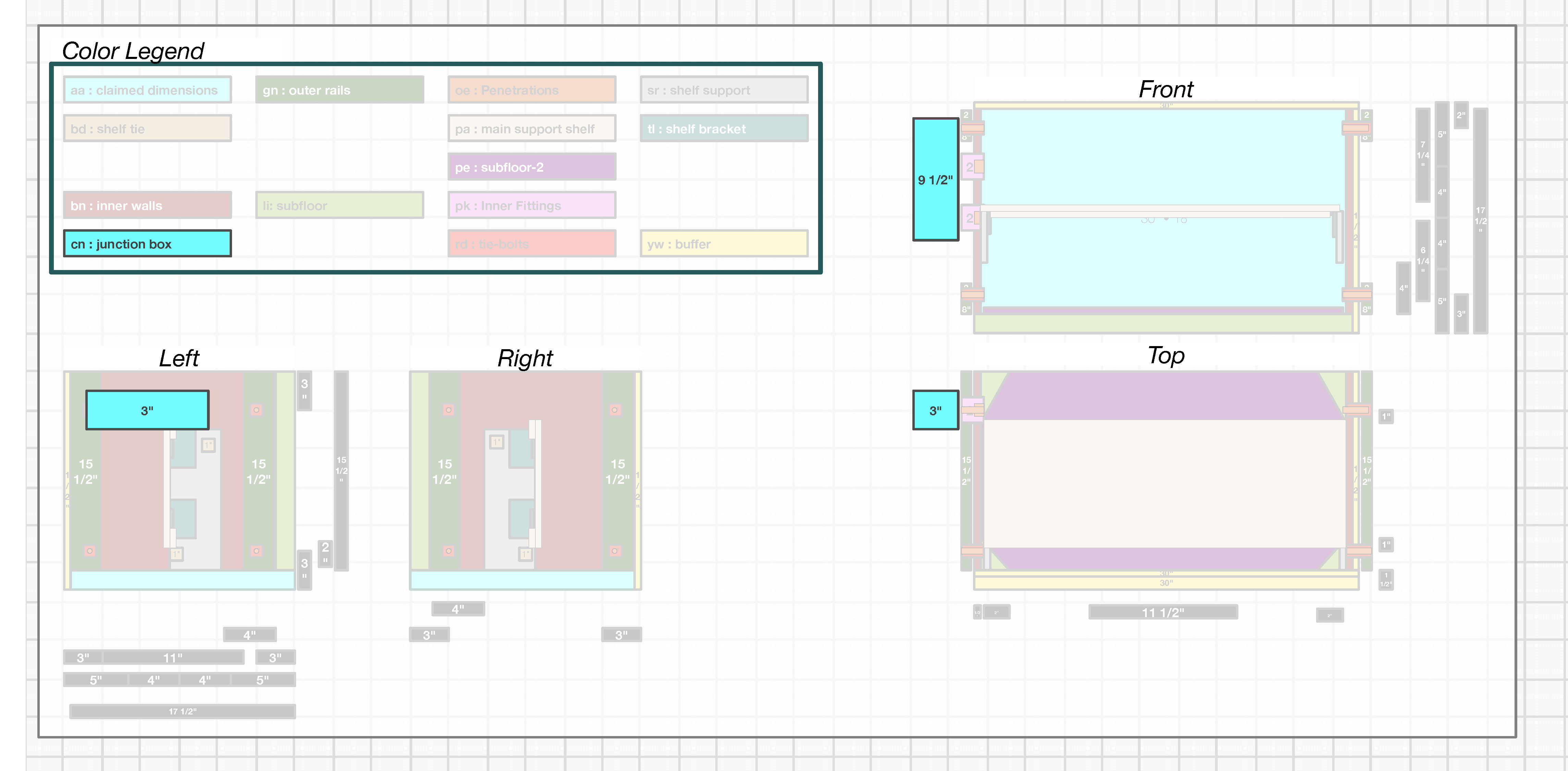
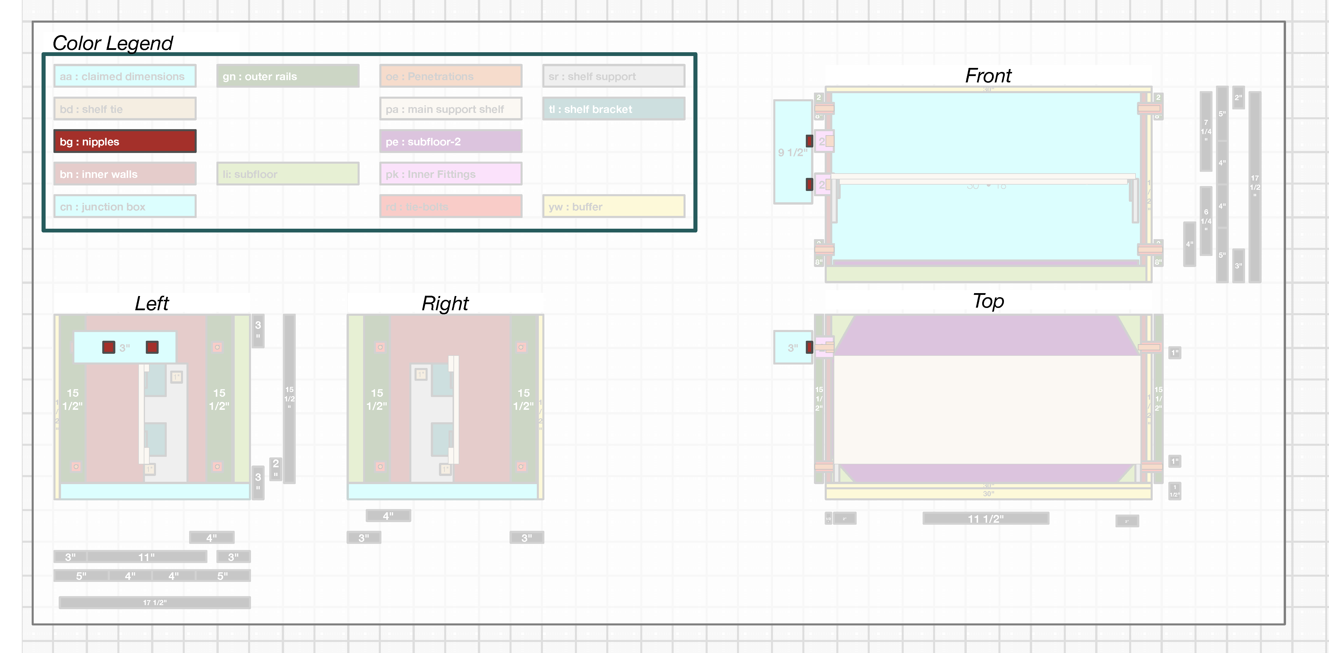
Note that the box is not attached to the rails: by attaching it to two hubs, it is secured to the side of the box without needing the rails. Hubs project a bit further than the rails: about 1” including a spacing and sealing washer. But the junction box is 3.3” high so there is a fair amount of flexibility in aligning the side of the junction box with whatever it is to attach to.
As of this step, the inside of the vault is connected with watertight hubs and seals to an IP67 junction box. This would be a state of the box where it is watertight and the outside is currently uncommitted to what electrical boxes and outlets it provides.
Outdoor Electrical Box
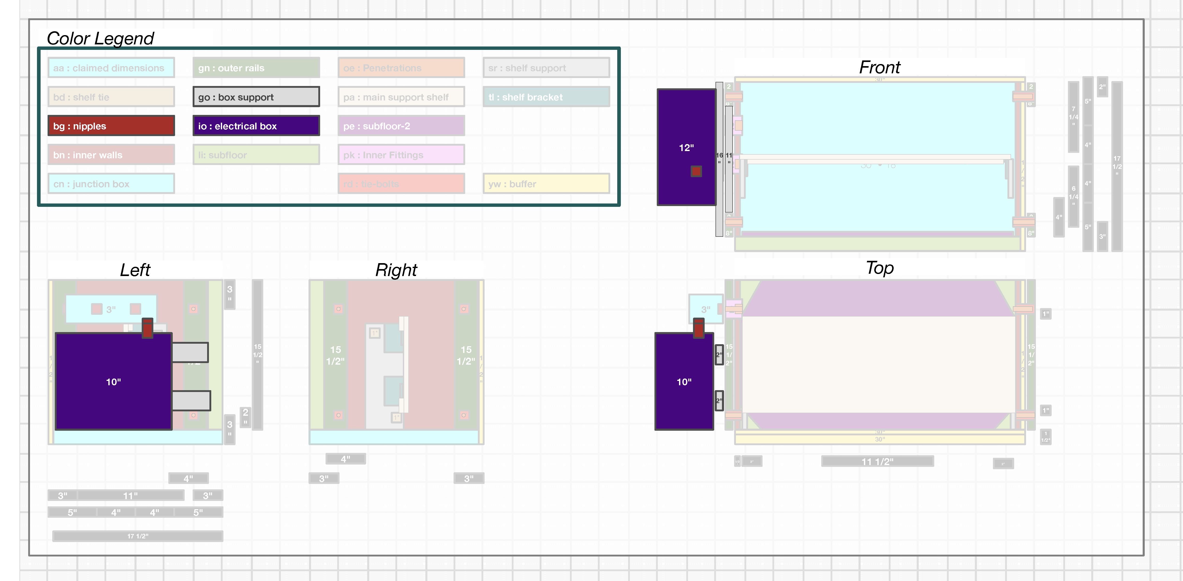
There are several different types of electrical boxes that are outdoor capable and provide different features. For Vault-1, the electrical box used is structural (things are attached to it), so it is a steel IP66 12x10x6” box. In the diagram the box is shown in indigo (‘io’) with vertical supports that span the rails shown in gainsboro (‘go’). The vertical supports both (a) span top-to-bottom of the rails and (b) are structurally laminated to another span for the inside 11” [minus a ½” buffer] distance between the rails. In this combination, they are a bit more than 1” in thickness so they can attach to the rails with ~1” screws and the electrical box can attach to them with ~1” screws.
The electrical box is attached to the junction box with hubs and nipples: shown as a single attachment point although multiple attachment points are possible. The junction box overlaps sides with the electrical box in about a 8”x1.5” area, so multiple connection locations can be chosen depending on the electrical box characteristics.
It is also always an option to connect the two boxes with a “U” through the bottoms of each, which would make sure the penetrations are always below the terminals.
Outlet Boxes
To provide AC outlets, Vault-1 attaches a mounting plate to the front-facing (left-side) of the electrical box. This utilizes the extra space the electrical box provides vs. putting the outlets on a different side (e.g. the right-side rails) or on a separate structure reached by conduit. To get to the outlet boxes, we could run conduit in a “U” or leverage another junction box to make wiring a bit easier to access.
The current Vault-1 uses the Junction Box approach shown in cyan (‘cy’) for the box, bug (‘bg’) for the nipples and hubs, green (‘gn’) for the added mounting plate, and navajo (‘no’) for the two outlet boxes. The smaller outlet box is a normal 1-gang box and is used for an inlet in Vault-5 but is currently unused in Vault-1. It could have a simple blank faceplate or the conduit could be longer and skip over it all the way to the larger outlet box.
The larger outlet box is a four-way outlet that is common in style to several Vaults although the outlet behavior can be different.
Vault-1 has historically had a feature that two of the AC outlets are only enabled if the other outlets are not being used. This is so the inverter is less likely to be asked to supply more than 1500 watts (which it gets angry if asked to do) in spite of having four outlets.
Vault-5 supports all four outlets running at the same time, but outlet pairs can also be disabled by automations so (for example) larger energy sources do not deplete a low battery. This can make sure the freezer is powered when the EV charging would drain the battery completely.
Summary
Finished diagram with all layers.
Next Design
Continuing to the next design, Vault-4 is similar in core design concepts but is significantly different with the following aspect changes:
- Larger vault (24x24xWidth) to hold 3+ 19” Rack batteries
- 4-level partial-span shelving to maximize non-battery space
- Significant levels of insulation
- Only DC (harvesting) circuitry but with multiple MPPTs
- Large conduit connection for high-amperage DC out (to Vault-5) as well as smaller conduit and anderson PP connectors to provide lower amperage DC to systems like Vault-1
- Semi-transplant and non-structural electrical box with status lights (as opposed to the structural version in Vault-1)
- A BRB (Big-Red-Button) for rapid shutdown