Packout Portable Electrical System
The following describes how to create a portable electrical system (storage, charging, and distribution) leveraging the Milwaukee® Packout™ storage system. The main benefits of this approach are:
- A very high level of portability (weight, transportability, weather resistance, etc.)
- Flexibility in configuration
- Good maximum power output (about 7.5kW)
- Good storage (10 kWh).
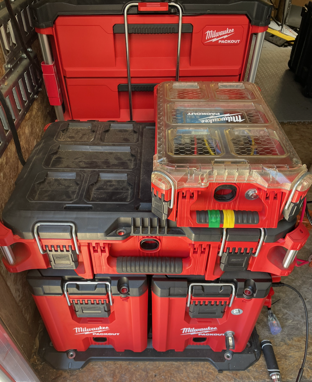
The following two images provide the general concept and approach:
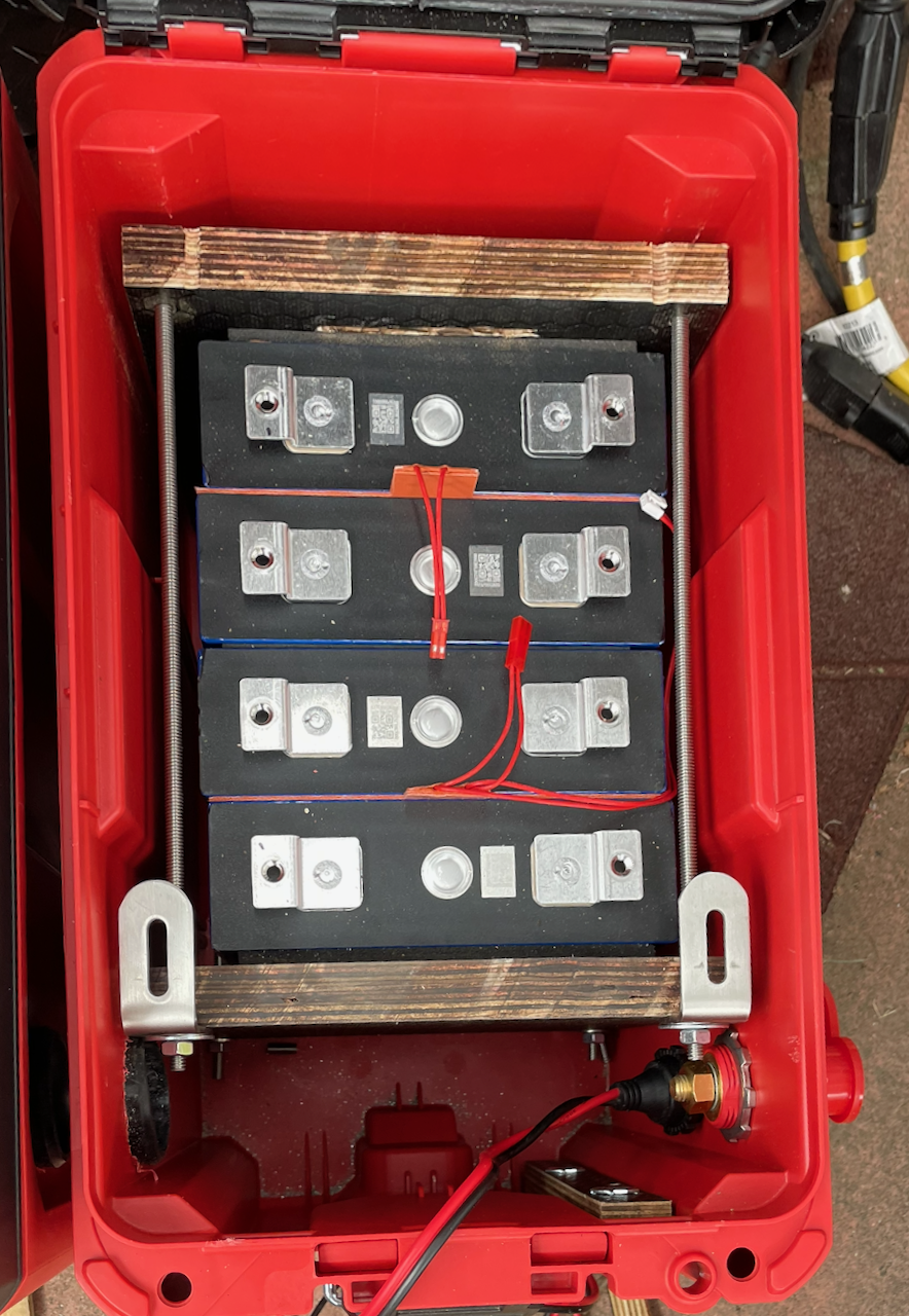
Wiring for a 200ah 12V cell
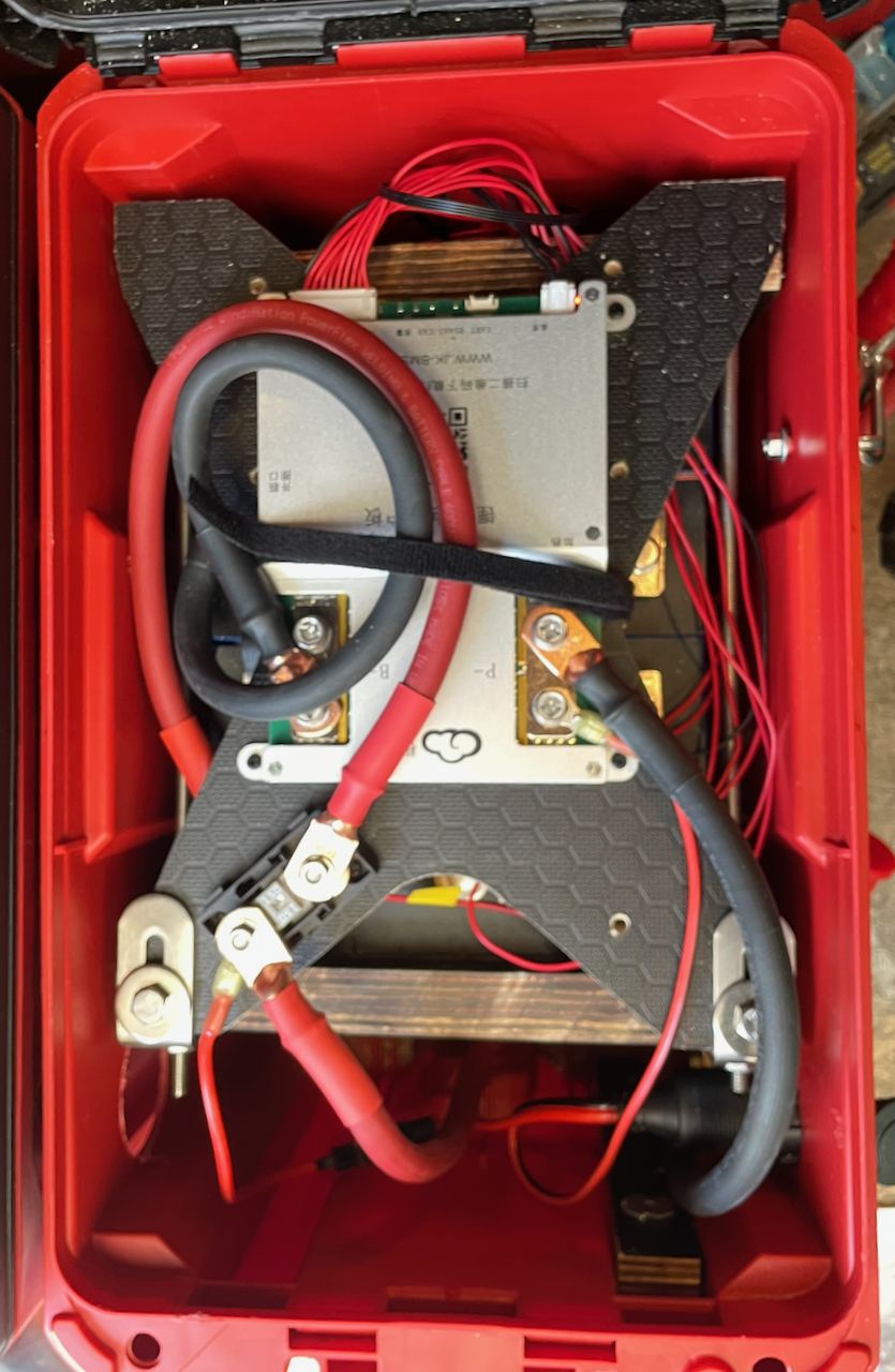
Connecting the system main DC stack and bus (for AC and Solar)
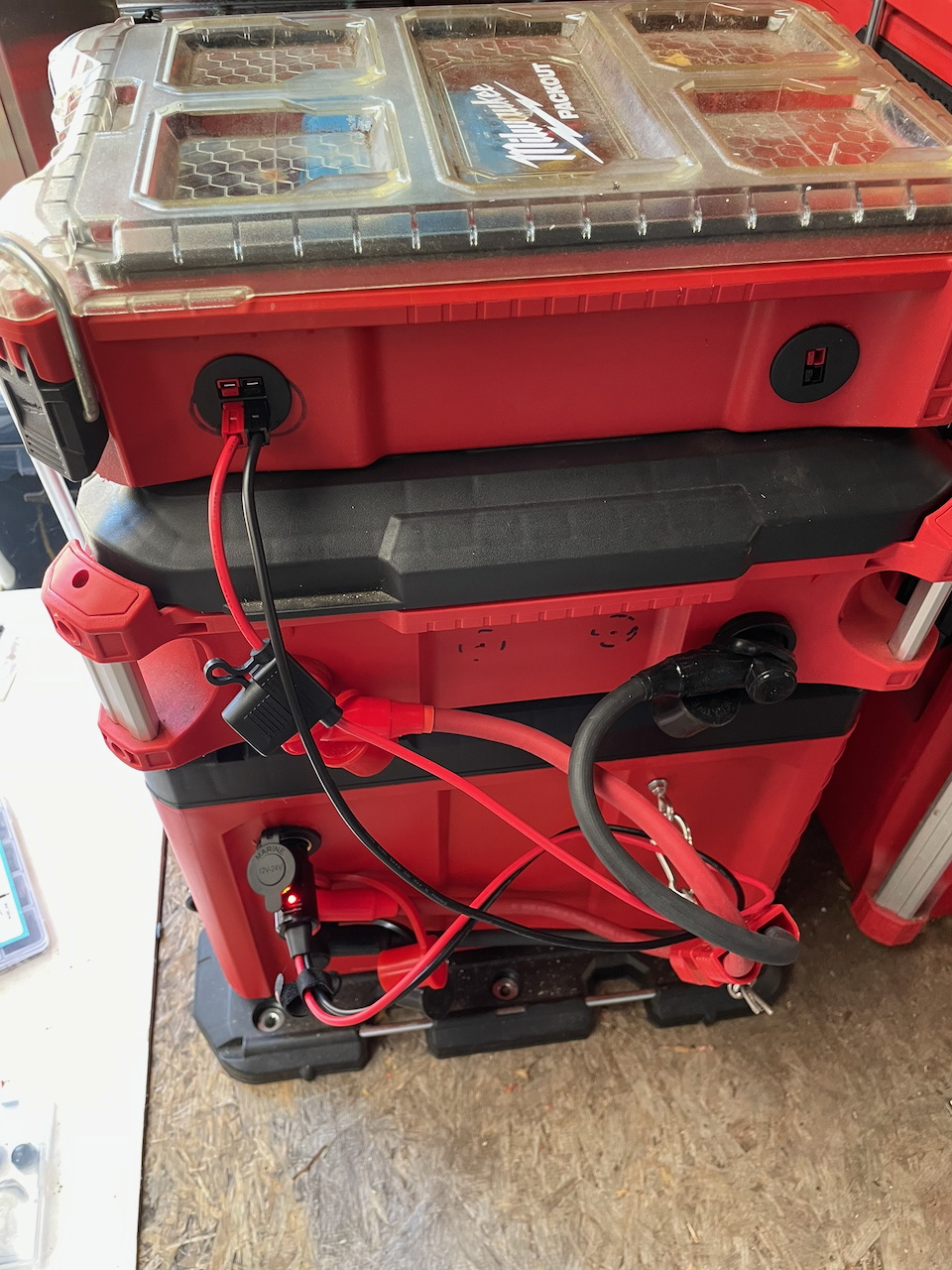
Table of Contents
Introduction
There are a number of tradeoffs in the different approaches to building an electrical system (defined as a system that has electrical storage, charging, and distribution).
- An all-in-one portable generator provides many desirable features in a relatively small form factor.
- A larger ‘installed’ system can have higher capacities for both power and storage.
- A ‘dolly’ combines some of the higher capacities into a somewhat moveable chassis.
With each of the benefits of the approaches just mentioned, there are potentially corresponding penalties to price, flexibility, portability, and so on.
Portability
One major consideration to enabling a system to be portable is that the weight of the components can not be beyond the abilities of the user to move them. For a generally useful electrical system the heaviest item is almost always going to be the battery, which weighs about 16-20 lbs (7-9kg) per kWh. Managing this weight will be one of core aspects to the modular approach. An additional requirement further defining portability is that it has to be possible to move the components without leveraging wheels and ramps. Components must be carryable within normal human comfort levels: less than 50lbs.
Beyond the portability considerations, the other aspects are:
- It should be possible to compose different variations for functional or financial goals;
- It should be possible to create a system with >5kW of power generation, and
- It should be possible to have more than 5kWh of storage
Additional Aspects
To meet the above goals, additional approach aspects were added to help focus the potential solutions. These include
- Leveraging the functionality and sizes of the Packout™ tool boxes and organizers
- Utilizing modern wireless control systems
- Using reasonably-sized wires (otherwise the wires themselves become a burden). This was ultimately constrained in the approach described to using wires no bigger than 35mm² (2 AWG), allowing a bit over 100A-sustained comfortably. [1]
- Having a clean connector system so the system can be assembled and disassembled as rapidly as possible [2]
Approach
A core approach described herein is to leverage an unusually good match between the dimensions of the Packout™ Compact Tool Box (“Ammo Box”) and the size of the 206Ah LiFePO4 prismatic cell. Four 206Ah cells easily fit in width, height, and depth within the compact toolbox. This produces a 12V nominal battery with room for a BMS on top and connectors in the forward section.
A second core approach is to use the sides of the Packout™ system as the connector location and ‘bus’ of the system. The main power bus can be on either side but in this version it is shown to be on the right side when facing a system stack. Since a Compact Tool Box is only half-width, there is also an internal portal between the left and right Tool Box that allows combining two boxes without external connection. Full-width boxes have access to both the left and the right side for either bus or additional port connections.
By using the sides instead of the front, back, or top, the system is easier to work with individually (multiple portal locations are available on the sides without impeding the toolbox functionality of hinges and stacking) and in standard Packout™ stacks of three or more layers (potentially on a dolly) where the sides are commonly accessible when the back (for example) would likely be inaccessible. At worse, a bit of breathing space needs to be maintained between stacks to allow for the ‘bus’ portals and wiring.
Walkthrough “Demo”
The following walks through a completed system to provide context for the subsequent description.
Compact Toolbox Battery
Four 206Ah prismatic cells (e.g. LF206: https://www.evlithium.com/LiFePO4-Battery/eve-prismatic-cells-206ah.html) can fit into the compact toolbox with room to spare on the sides, front, and top. To keep these cells in position and compressed to avoid expansion, they are sandwiched between two end plates.
Battery Sandwich
BMS Mounting
The battery is designed to have the BMS mounted above the cells, with easy access to the terminals for both power and sense/balance wires. As long as the leads are long enough, the top mounting plate can be removed with connections in place. Otherwise, power wires or the mounting harness will have to be disconnected.
Note to support the desired amperage of the system, all the power wires are 2AWG [35mm²] or equivalent (usually much higher) amperage busbars.
BMS Mounting with JK BMS
External Access
External access is through two ⅜” (M10) bulkhead pass-through terminals and one ‘portal’ which is most commonly a 20A Cigarette Lighter Port but could be anything of similar size. There is enough space for three 1.5” (40mm) portals on the side with 2” spacing where the shown example is using 1⅛” and 1¼” holes as needed.
External Access Ports
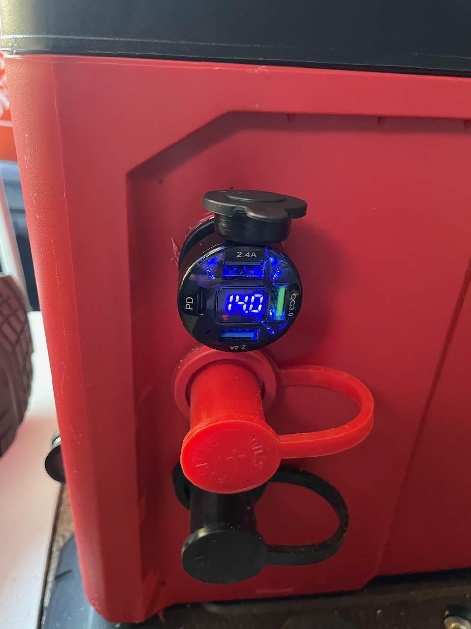
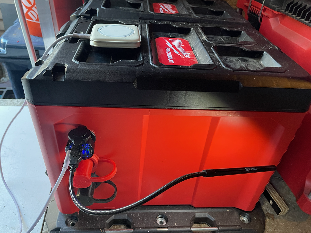
At this point, the compact toolbox battery is simply a 200Ah 12V DC battery with a cigarette lighter port and two more serious looking terminals.
Running with Cigarette Lighter Plugin
AC and Primary Power Bus
The main power bus is run between ⅜” (M10) bulkhead pass-through terminals that support about 200A (2/0 or 70mm² equivalent). The wires are 2AWG (35mm²) so the system is targeting a bit under 150A maximum continuous load, but should be able to handle transitory spikes above that without significant heating. Fuses are at 150A although possibly should be a bit higher if they are relatively fast acting.
The primary power bus is at whatever voltage is desired. Each compact toolbox battery ‘cell’ produces 12V but two can be combined horizontally for 24V and a total of four can be combined vertically for 48V nominal.
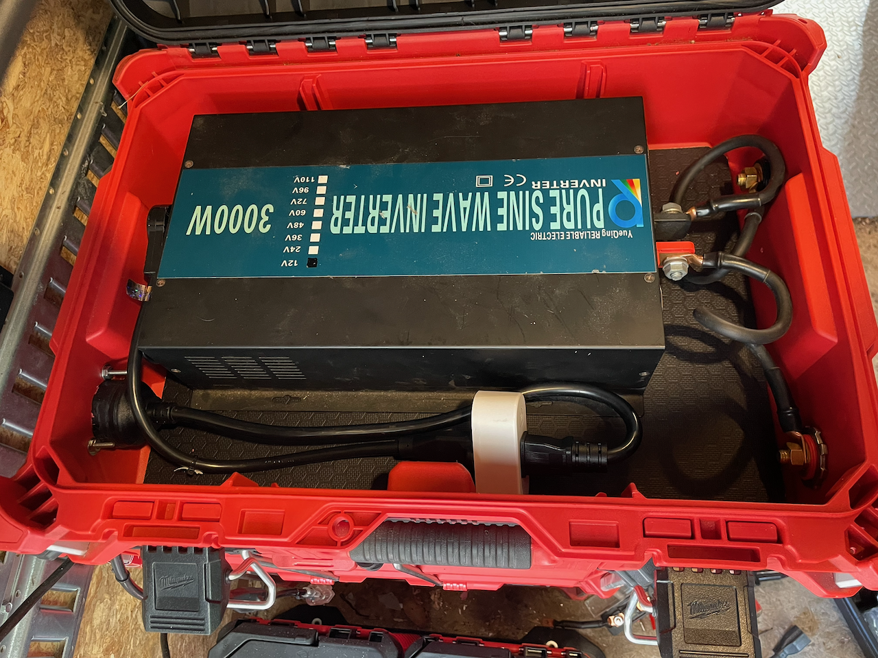
In the example, the primary power bus is running at 12V, so it can attach to other 12V components like a 12V to 120V AC inverter. The AC Inverter is in its own toolbox with ⅜” bulkheads to access the full ~150A. The inverter toolbox spans the full width of the Packout stack, so power can come in the right and the AC provided through a 5-15R port on the left.
AC Inverter Box
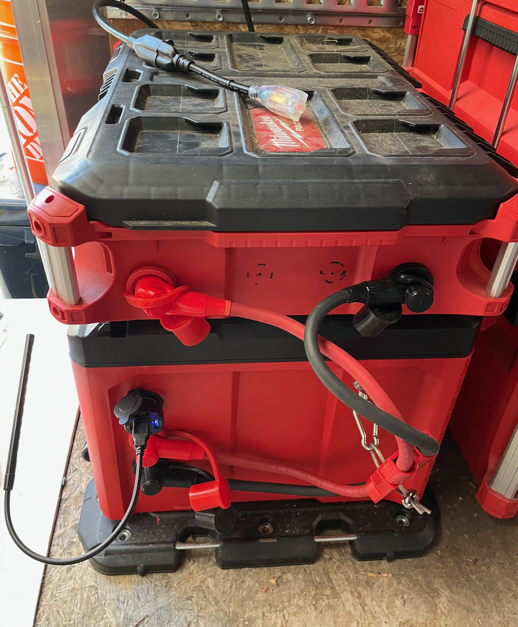
To enable the boxes to be easily assembled, connected, disconnected, and disassembled, Anderson SB-175 connectors are used. If the wires are long enough, it is possible to disassemble the stack while still keeping the components connected.
AC Inverter Box in Stack
Solar Power and Secondary Power Bus
Solar could hook into the primary power bus, but if it only needs to supply or consume 20A, it can also easily plug into the secondary power bus.
Using a Victron 100/20 MPPT with:
- System/Battery DC (up to 20A)
- Solar Input DC (< 20 amps)
- Load Output (up to 20A)
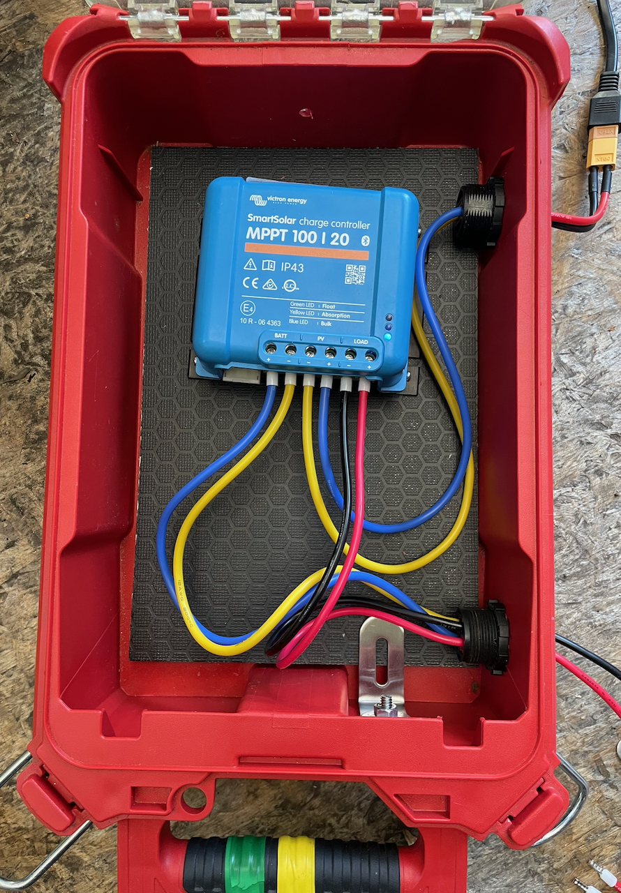
We can use a Compact Organizer with two sets of Anderson plugs to support the three connections. Using an organizer makes the lights of the MPPT visible without opening the lid, although it is bluetooth capable so sight visibility isn’t required.
The Solar box is connected with a Cigarette to Anderson PP45 cable for the 20A connection. For this example, there are an excessive number of fuses along the secondary power bus: it is fused in the battery itself, along this connector wire, and in the Victron also.
Solar MPPT Box
Solar MPPT Box in Stack
Solar MPPT Box in Stack (Front)
Secondary Power Bus
A secondary power bus is run at lower amperage through either Anderson PP45 or 20A Cigarette Lighter ports. The cigarette lighter port has the advantage of structural strength, easy accessory support, and is cheaper. The main advantage of using PP45 is that two 2-pole ports can be combined in the same space, and it supports 50% higher amperage.
Details
Most of the details of the build are pretty visible in the end result, but the following goes through some of the details.
The mounting plates are “Hex Ply” for the structural strength, heat resistance, and esthetics. Vertical surfaces are about an inch, where horizontal supported surfaces are a half inch.
The battery fuse is MIDI/AMI to reduce the space required and for consistency with the prismatic cells and BMS (that are commonly ¼” (M6) terminals).
The cigarette lighter port has the advantage of structural strength, easy accessory support, and is cheaper, so as long as only two-poles need to get out of the battery, it seems the better choice.
Future Installment
At this point the 12V version is fairly complete. Adding a second battery for capacity is possible but doesn’t change anything architecturally: there would simply be a pass-through connector between the two battery boxes.
The next notable version will likely be a 24V version with a balancer, shunt, and a higher-power solar and AC charger (using the primary bus to access 50-100A charging capability). It may also have a Victron Cerbo for remote monitoring via Wi-Fi and VRM.
Footnotes
- [1] Conceptually it would be possible to get all the way to 200A, but the wires would have to be significantly heavier and some space constraints would be hard to meet.
- [2] The connectors add an expense that can be avoided in exchange for longer setup and teardown times but without any loss of functionality otherwise..